
Clearance adjusting device for disc brake

A technology of a gap adjustment device and a disc brake, which is applied in the field of rail vehicles, can solve the problems of large space occupation, complex structure and difficult layout, and achieve the effects of low space occupation, simple structure and low production cost.

Pending Publication Date: 2020-06-23
CRRC QISHUYAN INSTITUTE CO LTD
View PDF0 Cites 3 Cited by
  • Summary
  • Abstract
  • Description
  • Claims
  • Application Information

AI Technical Summary

Problems solved by technology

In this way, although the existing gap adjustment device can also adjust the brake gap to keep the brake gap stable, it needs to be equipped with a driving device to drive the gap adjustment device, which has complex structure, high cost, large space occupation, and is difficult to arrange.

Method used


Image

  • Clearance adjusting device for disc brake
  • Clearance adjusting device for disc brake
  • Clearance adjusting device for disc brake

Examples


Embodiment Construction

[0029] Embodiments of the present invention are described in detail below, examples of which are shown in the drawings, wherein the same or similar reference numerals designate the same or similar elements or elements having the same or similar functions throughout. The embodiments described below by referring to the figures are exemplary only for explaining the present invention and should not be construed as limiting the present invention.

[0030] First of all, in the prior art, friction plates are arranged on both sides of the brake disc of the disc brake, the rear friction plates are fixedly connected to the piston, and the piston can move axially along the floating caliper body; the motor stator is installed on the floating caliper body, and the motor rotor It is connected with the center wheel of the planetary gear reduction mechanism, the planet carrier is fixedly connected with the lead screw, and the lead screw and the threaded hole of the spline shaft form a thread t...


PUM


Abstract

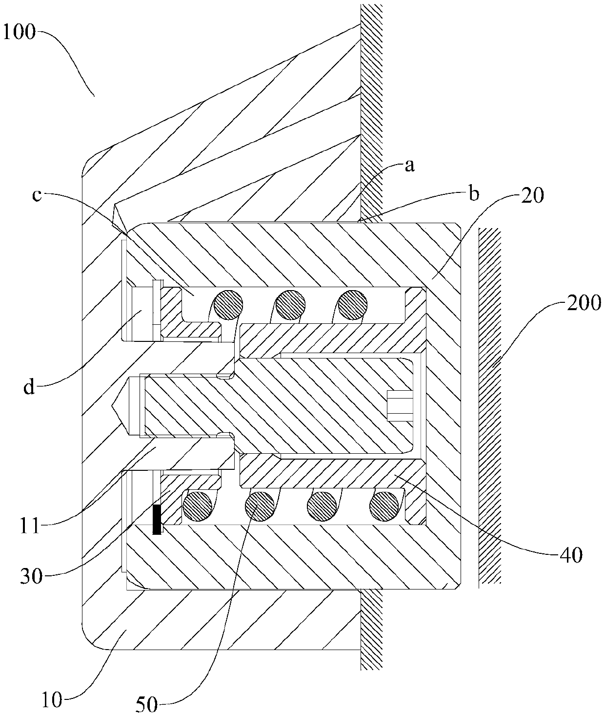
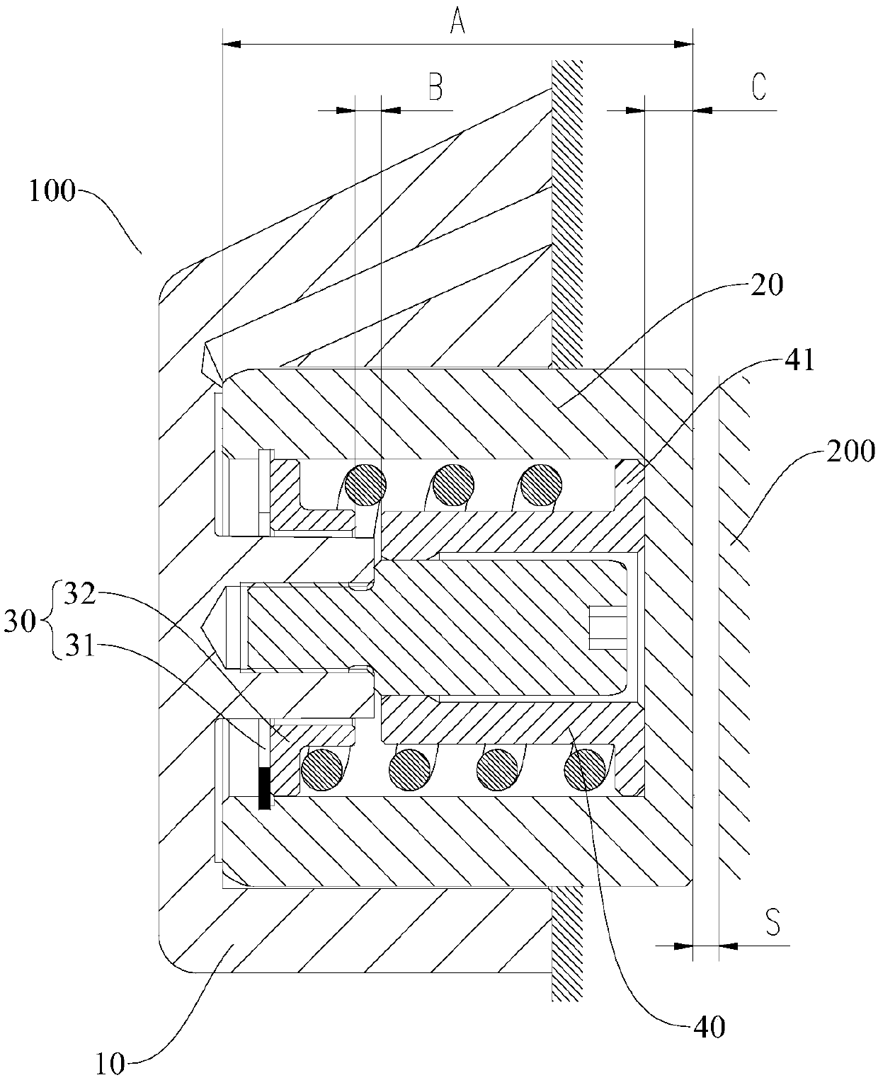
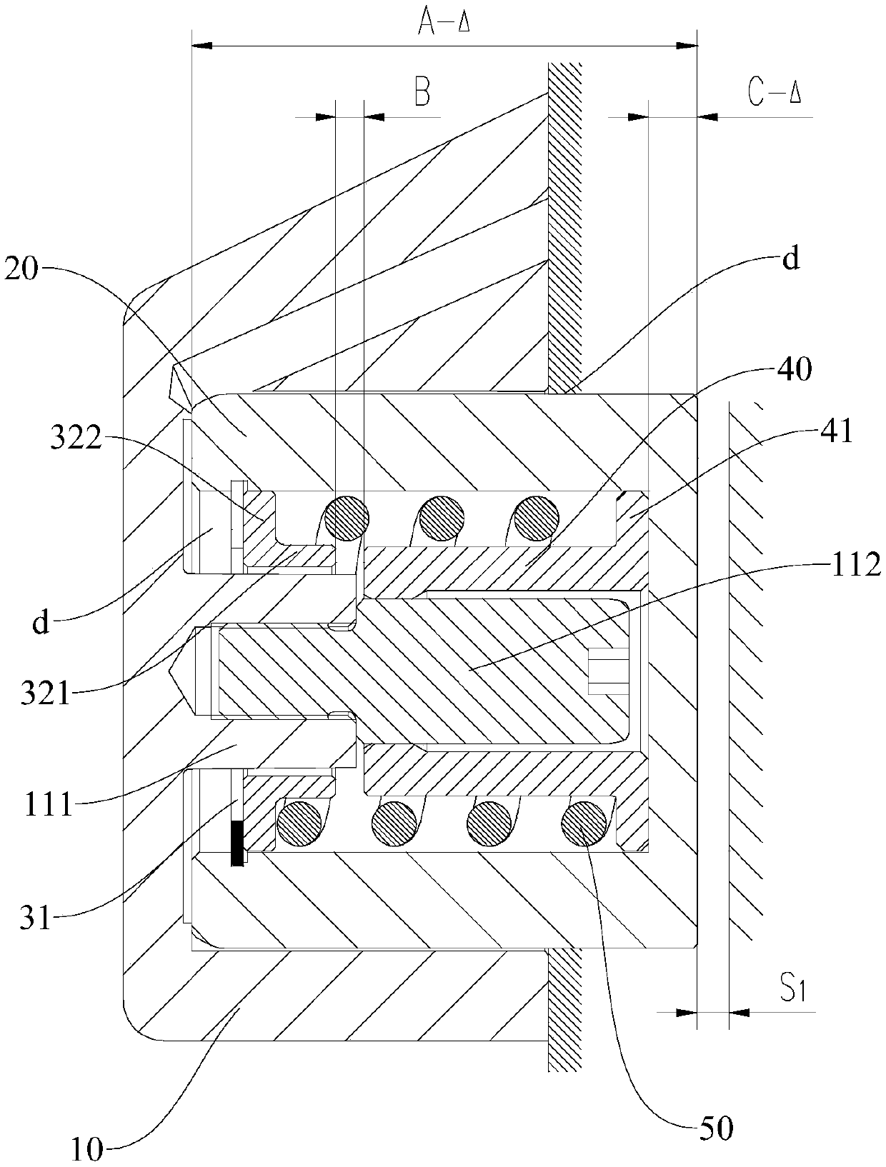
The invention discloses a clearance adjusting device for a disc brake. The clearance adjusting device comprises a cylinder shell, a piston, a stopping assembly, a tensioning sleeve and an elastic part. A movable channel is arranged in the cylinder shell, and one end of the movable channel is open to form an opening part. A fixed boss extending towards the opening part is arranged on the bottom wall of the movable channel. The piston is movably arranged in the movable channel, the outer side of the bottom wall of the piston stretches out of the opening part, and a friction sheet is arranged onthe outer side of the bottom wall of the piston. The blocking assembly is arranged in a mounting chamber, and can be driven by the piston to move. The tensioning sleeve is arranged on the fixed boss,and is in clearance fit with the fixed boss. The tensioning sleeve and the stopping assembly are aligned to each other and are separated. One end of the elastic part is connected with the stopping assembly, and the other end of the elastic part is connected with the tensioning sleeve. Thus, on one hand, the braking clearance is kept stable, and the braking response time and the braking effect areboth kept stable; and on the other hand, a driving part and a transmission assembly do not need to be arranged, the structure is simpler, the occupied space is small, and the production cost is low.

Description

technical field [0001] The invention relates to the technical field of rail vehicles, in particular to a clearance adjusting device for disc brakes. Background technique [0002] Engineering vehicles mostly use brakes with no backlash adjustment function. This type of brake injects brake fluid with a certain pressure into the oil cylinder, pushes the piston to move, and then drives the friction plate and compresses the brake disc to realize the braking of the vehicle. The structure of this type of brake is simple, the technology is mature, and the price Inexpensive and stable braking performance. However, after the brake disc of the above-mentioned traditional brake without the clearance adjustment function is worn out, the clearance adjustment cannot be performed, which will reduce the braking effect and increase potential safety hazards. [0003] Furthermore, in the related art, the brake with the gap adjustment function generally realizes the gap compensation through th...

Claims


Application Information

Patent Timeline
IPC IPC(8): F16D65/72F16D65/76
CPCF16D65/72F16D65/76
Inventor 孙龙跃周骥金钱余王阳
Owner CRRC QISHUYAN INSTITUTE CO LTD
Learn More