
Pressure gauge for high pressure vessel

A technology of high-pressure containers and pressure gauges, which is applied in the direction of piston-type fluid pressure measurement, fluid pressure measurement, instruments, etc., can solve the problems of reduced measurement accuracy in low-pressure areas and limited effective measurement range of pressure gauges, and achieves easy calibration, Large deformation capacity, the effect of improving axial deformation capacity

Active Publication Date: 2020-06-23
于霄鹏
View PDF6 Cites 0 Cited by
  • Summary
  • Abstract
  • Description
  • Claims
  • Application Information

AI Technical Summary

Problems solved by technology

However, for the safety and durability of the existing pressure gauges under high-pressure working conditions, the measurement accuracy in the low-pressure area will be affected, so that the effective measurement range of the pressure gauge is less

Method used


Image

  • Pressure gauge for high pressure vessel
  • Pressure gauge for high pressure vessel
  • Pressure gauge for high pressure vessel

Examples


Embodiment Construction

[0016] The standard parts used in the present invention can be purchased from the market, and the special-shaped parts can be customized according to the instructions and the accompanying drawings. The specific connection methods of each part adopt mature bolts, rivets, welding in the prior art , pasting and other conventional means, no longer described in detail here.

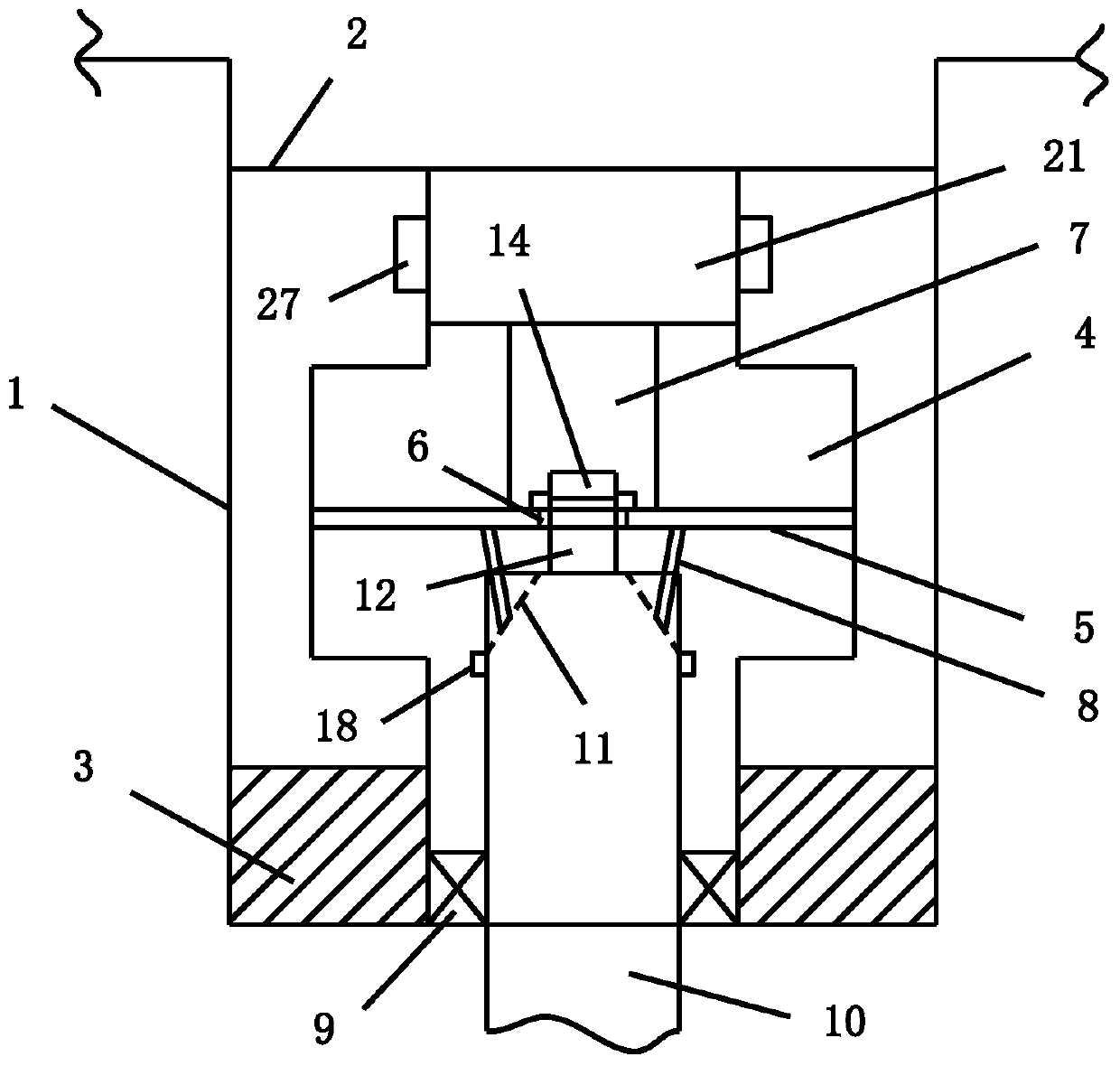
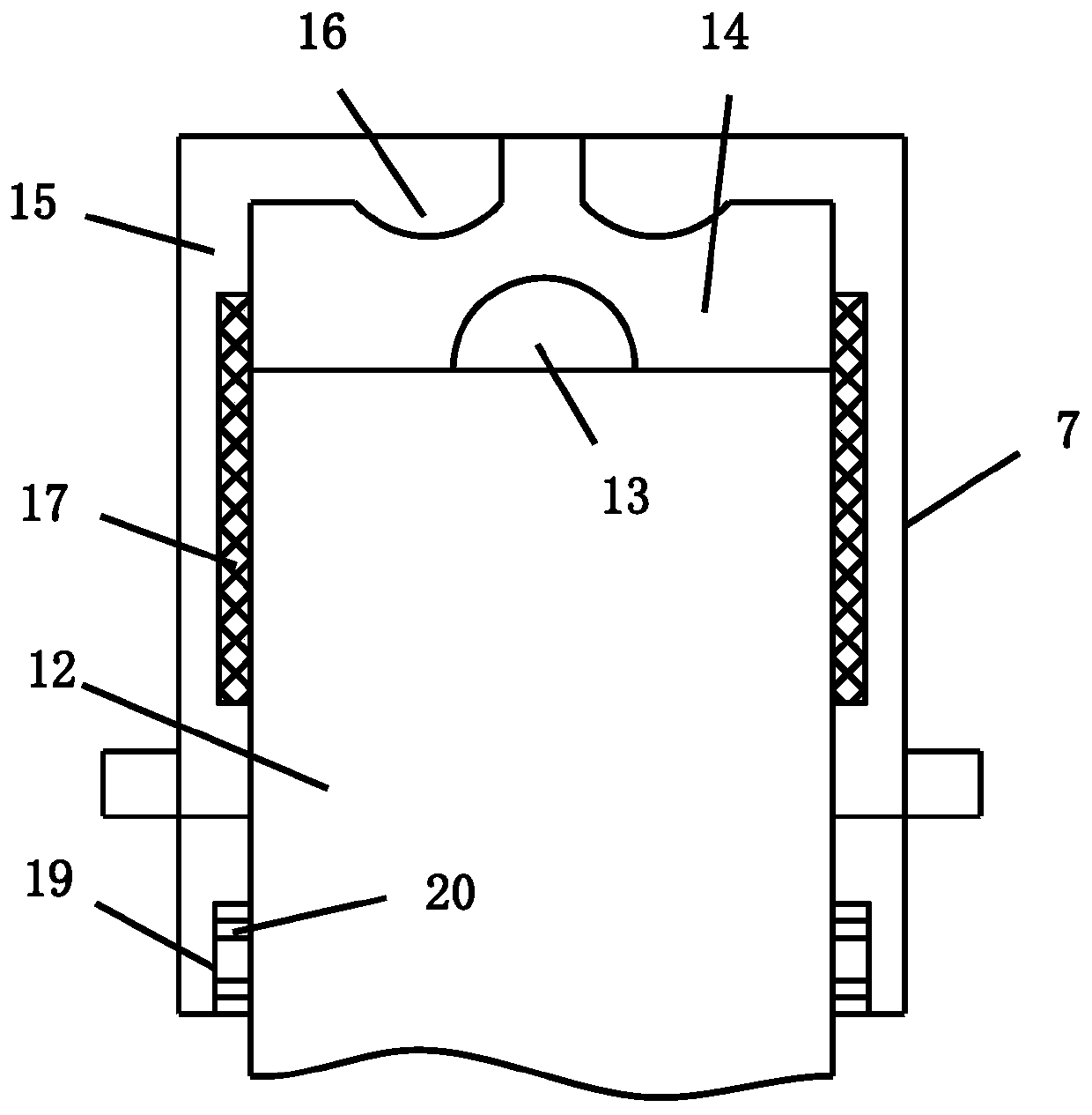
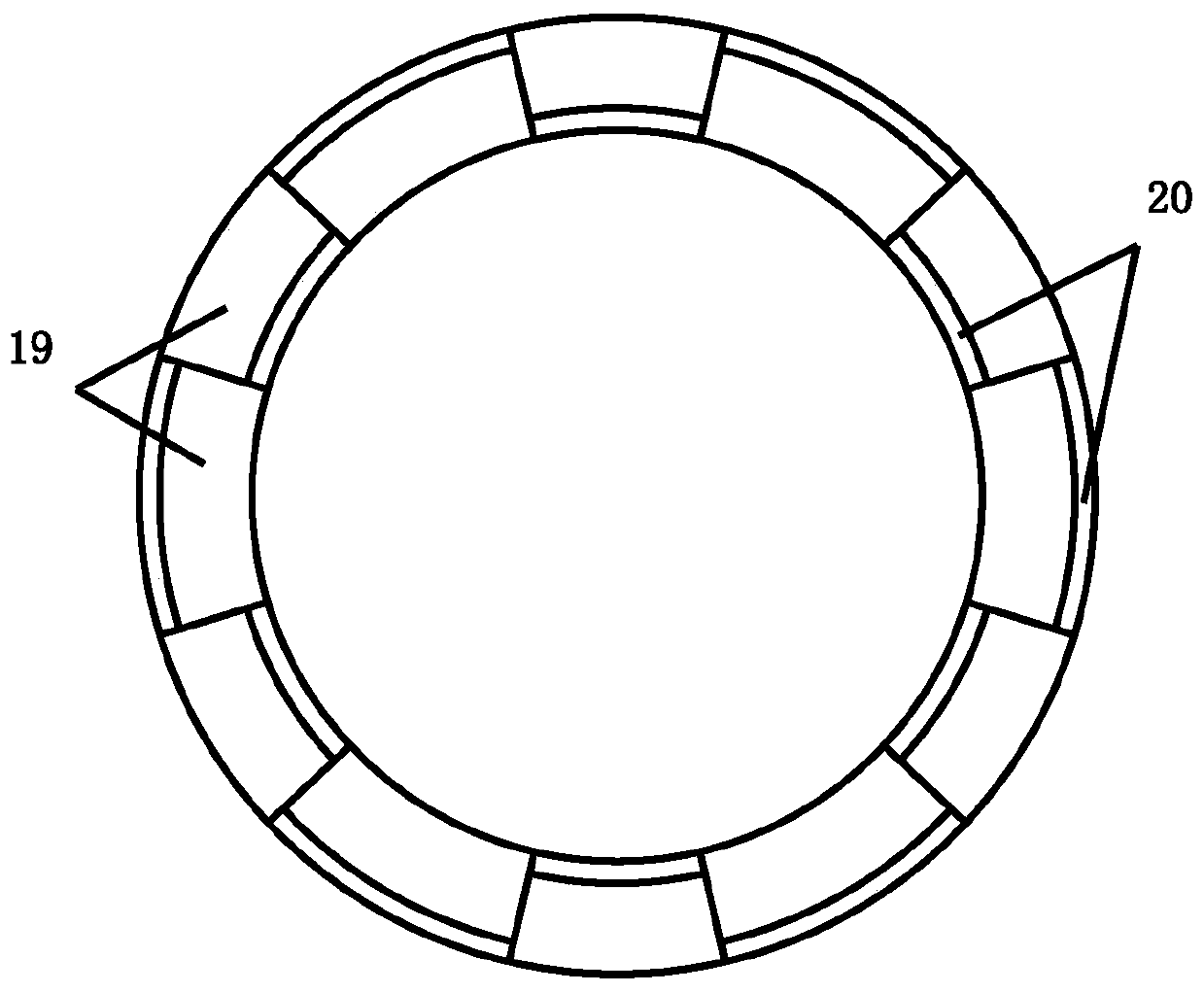
[0017] refer to Figure 1-4 , a specific embodiment of the present invention includes an outer shell 1, the top of the outer shell 1 is connected with a meter head 2, the bottom of the outer shell 1 is provided with a threaded part 3, the outer shell 1 is provided with a diaphragm cavity 4, and the diaphragm cavity 4 is fixed with a Diaphragm 5, the center of diaphragm 5 is provided with a through hole 6, the edge of the top surface of the through hole 6 is fixed with a jacking inner core 7, and the outer side of the jacking inner core 7 is sleeved with a jacking jacket 21, and the jacking jacket 21 is connect...


PUM


Abstract

The invention discloses a pressure gauge for a high pressure vessel. An outer shell is included, a top of the outer shell is connected with a gauge head; a threaded part is arranged at a bottom of theouter shell; a diaphragm cavity is arranged in the outer shell; a diaphragm is fixed in the diaphragm cavity; a through hole is arranged in a center of the diaphragm; a jacking inner core is fixed onan edge of a top surface of the through hole; an outer side of the jacking inner core is connected with a jacking outer sleeve; the jacking outer sleeve is connected with the gauge head; a pluralityof first elastic sheets are fixed on the edge of the bottom surface of the through hole; a bottom end of each first elastic sheet is obliquely arranged towards an axial direction of the through hole;and a sealing ring is fixed to the bottom of the outer shell, a piston rod is movably inserted into an inner side of the sealing ring, first sliding grooves in one-to-one correspondence with the firstelastic pieces are arranged in the edge of the top surface of the piston rod, a cylindrical lifting pin is arranged in a center of the top surface of the piston rod, and a spherical protrusion is arranged on the top surface of the cylindrical lifting pin. Defects in the prior art can be overcome, and measurement accuracy of a low-pressure area is improved while safety of the pressure gauge is guaranteed.

Description

technical field [0001] The invention relates to a metering and testing device, in particular to a pressure gauge for a high-pressure container. Background technique [0002] The pressure gauge is a measuring device used to detect the pressure. In order to ensure the safety of the high-pressure vessel, it is necessary to monitor the pressure inside the high-pressure vessel by installing a pressure gauge. However, for the safety and durability of the existing pressure gauges under high-pressure working conditions, the measurement accuracy in the low-pressure area will be affected, so that the effective measurement range of the pressure gauge is limited. Contents of the invention [0003] The technical problem to be solved by the present invention is to provide a pressure gauge for high-pressure containers, which can solve the deficiencies of the prior art and improve the measurement accuracy of the low-pressure area while ensuring the safety of the pressure gauge. [0004] ...

Claims


Application Information

Patent Timeline
Patent Type & Authority Applications(China)
IPC IPC(8): G01L7/16G01L19/06
CPCG01L7/16G01L19/06G01L19/0618
Inventor 辛成辉
Owner 于霄鹏
Learn More