Civil engineering structure anti-seismic test device

A technology of civil engineering structure and seismic test, applied in the direction of machine/structural component test, measuring device, vibration test, etc., to achieve the effect of ensuring accuracy, convenient control and simple structure

Active Publication Date: 2020-06-23
HENAN POLYTECHNIC UNIV
View PDF9 Cites 13 Cited by
  • Summary
  • Abstract
  • Description
  • Claims
  • Application Information

AI Technical Summary

Problems solved by technology

[0004] The purpose of the present invention is to design a kind of anti-seismic test device of civil engineering structure, which is used to solve the above deficiencies of the existing anti-seismic test device of civil engineering, so that the anti-seismic test device can generate shear waves in different directions to carry out anti-seismic simulation of the model, and can simultaneously The amplitude can be effectively adjusted to adjust the comprehensiveness and accuracy of the seismic test data

Method used


Image

  • Civil engineering structure anti-seismic test device
  • Civil engineering structure anti-seismic test device
  • Civil engineering structure anti-seismic test device

Examples


Embodiment 1

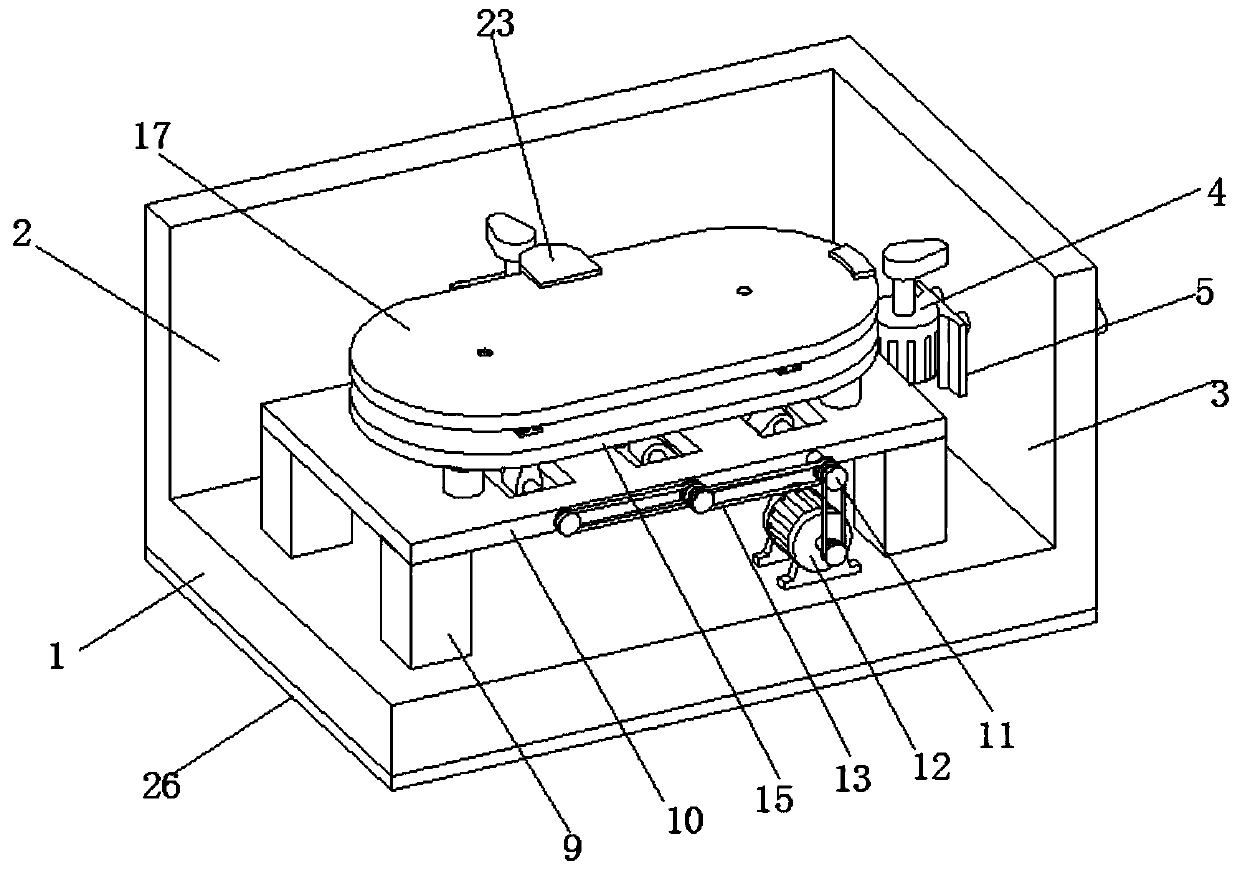
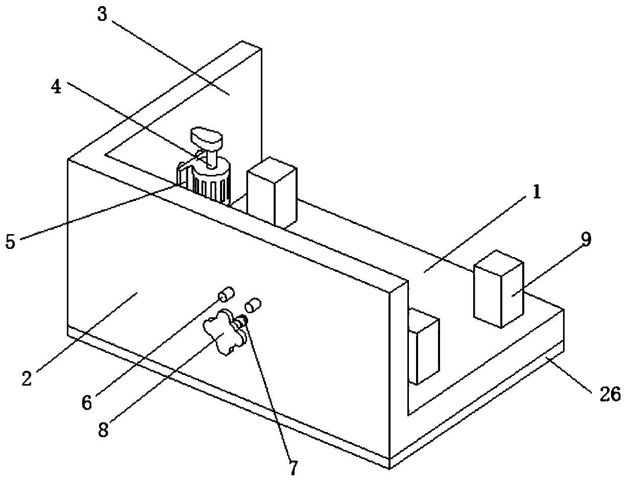
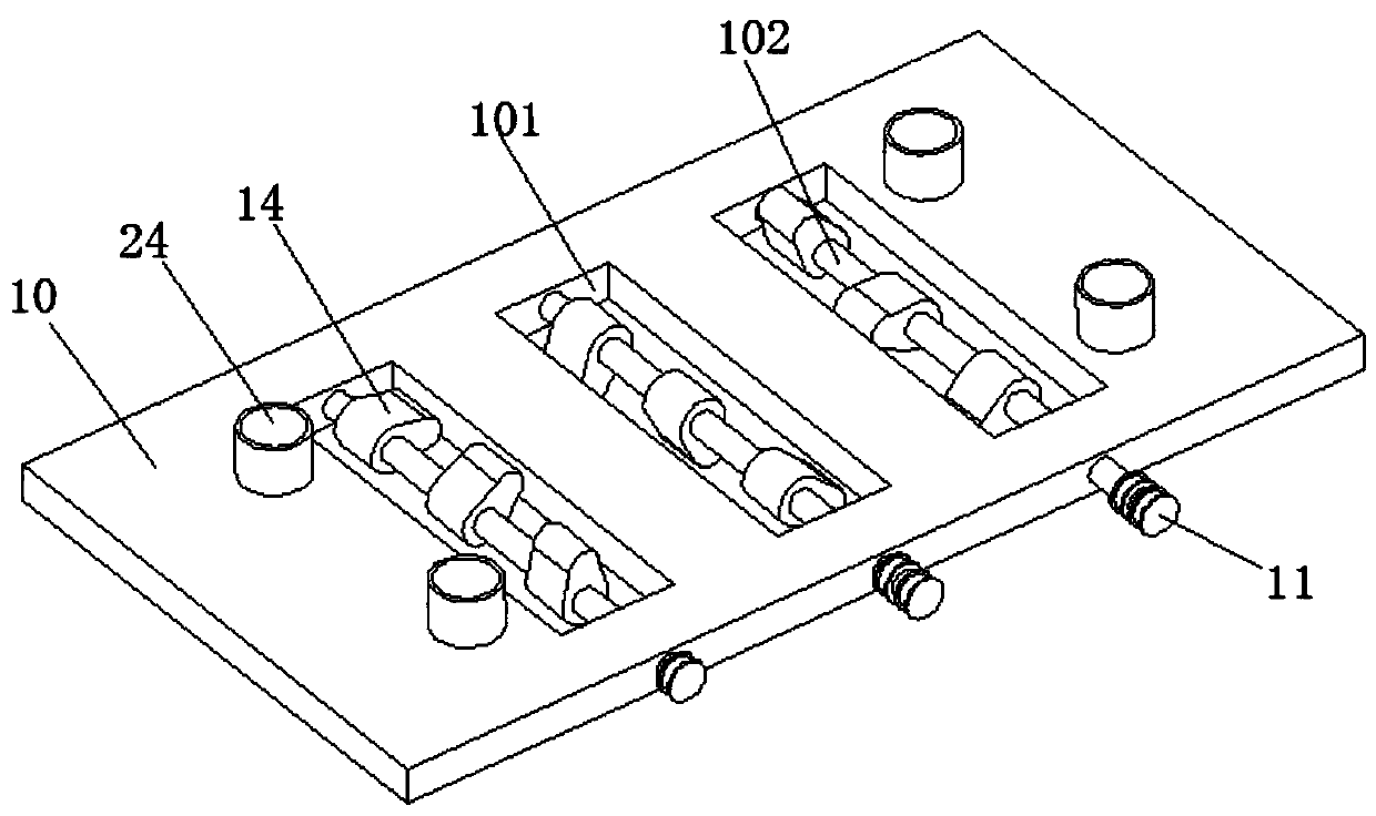
[0033]Embodiment 1 discloses an anti-seismic test device for a civil engineering structure, which includes a base plate 1 . In order to improve the shock and noise reduction effect of the entire device, a rubber shock absorbing pad 26 is provided on the lower surface of the base plate 1 . A first side plate 2 and a second side plate 3 are arranged on the side of the bottom plate 1 , and the first side plate 2 and the second side plate 3 are arranged perpendicular to each other. The inner surface of the first side plate 2 and the second side plate 3 is provided with an exciting motor 4, the output shaft of the exciting motor 4 is provided with a cam (not marked in the figure), and the exciting motor 4 is arranged on the fixed plate 5 Above, two sliding rods 6 are arranged on the fixed plate 5, two sliding holes are opened on the first side plate 2 and the second side plate 3, the sliding rod 6 passes through the sliding holes, and is located below the middle of the two sliding h...

Embodiment 2

[0037] Embodiment 2 is a further improvement on the basis of Embodiment 1, mainly adding the function of simulating shear waves in different directions, which will be introduced in detail below.

[0038] It includes a bottom plate 1, and in order to improve the shock absorption and noise reduction effect of the whole device, a rubber shock absorbing pad 26 is arranged on the lower surface of the bottom plate 1. A first side plate 2 and a second side plate 3 are arranged on the side of the bottom plate 1 , and the first side plate 2 and the second side plate 3 are arranged perpendicular to each other. The inner surface of the first side plate 2 and the second side plate 3 is provided with an exciting motor 4, the output shaft of the exciting motor 4 is provided with a cam (not marked in the figure), and the exciting motor 4 is arranged on the fixed plate 5 Above, two sliding rods 6 are arranged on the fixed plate 5, two sliding holes are opened on the first side plate 2 and the...


PUM


Abstract

The invention relates to the technical field of building test devices. The invention particularly relates to a civil engineering structure anti-seismic test device. The device comprises a bottom plate, a first side plate and a second side plate are arranged on the side face of the bottom plate. The first side plate and the second side plate are perpendicular to each other. Excitation motors are arranged on the inner side faces of the first side plate and the second side plate. A cam is arranged on an output shaft of the excitation motor; the excitation motor is arranged on the fixed plate; twosliding rods are arranged on the fixing plate, two sliding holes are formed in each of the first side plate and the second side plate, the sliding rods penetrate through the sliding holes, a threadedhole is formed below the position between the two sliding holes, a screw rod is connected into the threaded hole in a threaded mode, the inner end of the screw rod is connected with the fixing plate,and a longitudinal wave generating plate is welded to the upper ends of the stand columns together; according to the device, vertical longitudinal waves and horizontal transverse waves can be generated for simulating the earthquake state, the simulated longitudinal waves are closer to the earthquake state, and the accuracy of the earthquake resistance test is effectively ensured.

Description

technical field [0001] The invention relates to the technical field of building test devices, in particular to an anti-seismic test device for civil engineering structures. Background technique [0002] In large-scale civil engineering such as housing and bridge design, after the design drawings are completed, models are often made to verify the feasibility of the design scheme and drawings. After the model is completed, various simulation tests are required to To ensure the stability and reliability of the structure, the seismic test is an indispensable one among many tests. Among them, the earthquake resistance of civil engineering structures is mainly to simulate earthquakes, which are mainly divided into longitudinal waves and shear waves. First, the propagation direction of the longitudinal wave is parallel to the vibration direction, causing the building to vibrate up and down (refer to the attached Figure 8 ), then when a shear wave occurs, the propagation direction...

Claims


Application Information

Patent Timeline
Patent Type & Authority Applications(China)
IPC IPC(8): G01M7/06
CPCG01M7/022G01M7/06
Inventor 张向冈成香莉丁亚红王兴国陈旭牛海成徐海宾
Owner HENAN POLYTECHNIC UNIV
Why Eureka
Try Eureka