
Pressure detection system after high-pressure rubber tube production

A high-pressure hose and detection system technology, applied in the direction of applying stable tension/pressure to test the strength of materials, measuring devices, instruments, etc., can solve the problems of high pressure, inconvenient storage and carrying, increase manufacturing costs and maintenance funds, etc. Stability, the effect of improving gripping stability

Inactive Publication Date: 2020-06-23
宛兴怀
View PDF0 Cites 2 Cited by
  • Summary
  • Abstract
  • Description
  • Claims
  • Application Information

AI Technical Summary

Problems solved by technology

[0004] In order to solve the above problems, the present invention provides a pressure detection system after the production of high-pressure rubber hoses, which can solve the traditional detection. Usually, the pressure-bearing capacity of high-pressure rubber hoses is measured by increasing or decreasing the weight of the repressed products. Due to the large number of repressed products, its It is inconvenient to store and carry. Because the weight of the stacked compacts is equal, the high-pressure hose may not be completely flattened before stacking, and there may be excessive pressure when stacking another compact. At this time , the measured pressure of the high-pressure hose is relatively inaccurate. When clamping the high-pressure hose, due to the different radii of the pipe body and the internal cavity structure, corresponding fixtures are required for its internal support and external clamping. Different specifications Fixture production increases manufacturing costs and later maintenance funds and other issues

Method used


Image

  • Pressure detection system after high-pressure rubber tube production
  • Pressure detection system after high-pressure rubber tube production
  • Pressure detection system after high-pressure rubber tube production

Examples


Embodiment Construction

[0028] In order to make the technical means, creative features, goals and effects achieved by the present invention easy to understand, the present invention will be further described below in conjunction with specific illustrations. It should be noted that, in the case of no conflict, the embodiments in the present application and the features in the embodiments can be combined with each other.

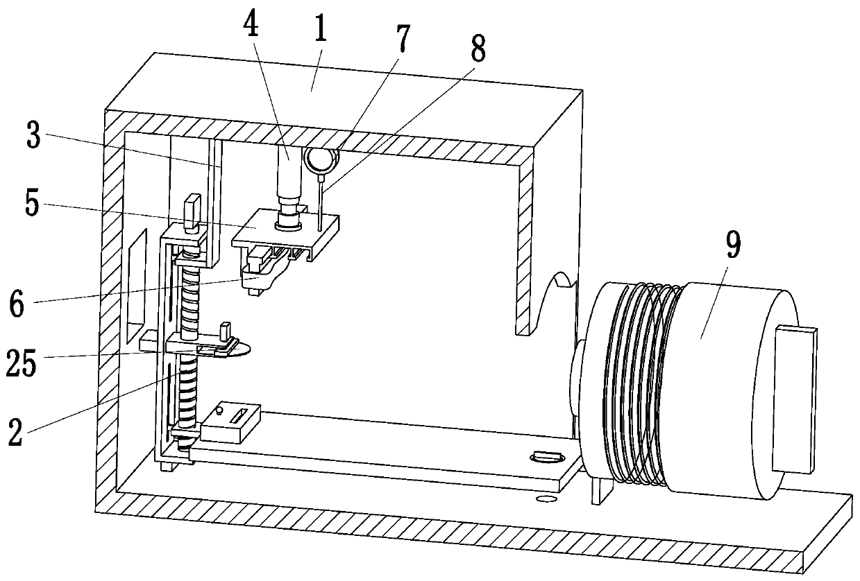
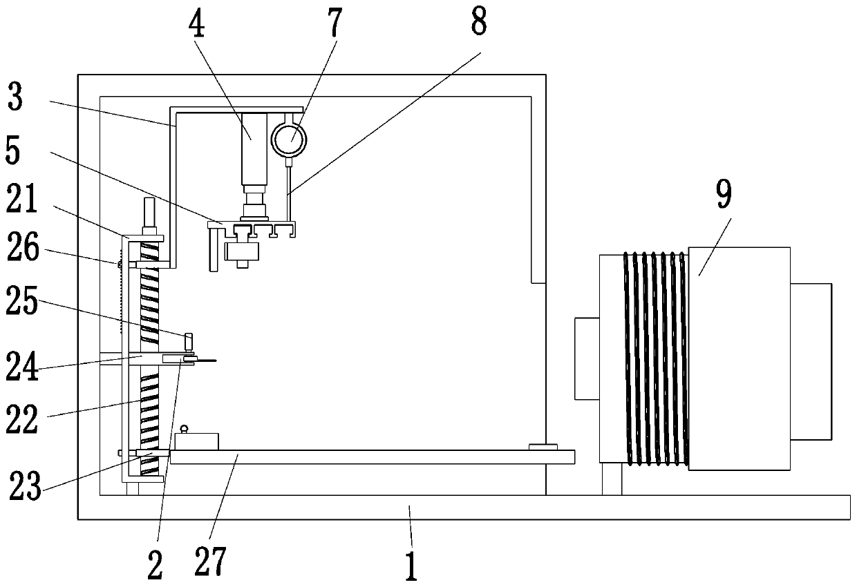
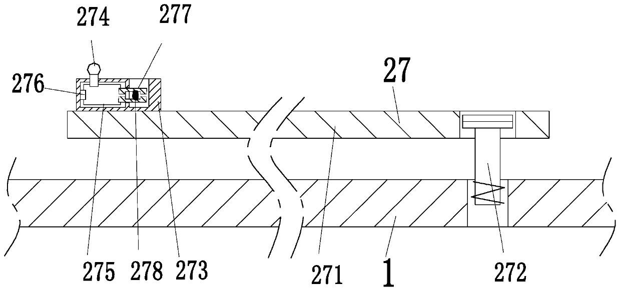
[0029] Such as Figure 1 to Figure 6 As shown, a pressure detection system after production of high-pressure rubber hose, including frame 1, adjusting device 2, connecting frame 3, driving cylinder 4, embedded plate 5, multi-purpose pressing head 6, pressure gauge 7, connecting rope 8 and sleeve device 9 , the left end of the frame 1 is equipped with an adjusting device 2, the frame 1 is made of transparent material, the connecting frame 3 is installed on the right side of the upper end of the adjusting device 2, the driving cylinder 4 is installed on the left side of the upper end o...


PUM


Abstract

The invention provides a pressure detection system after high-pressure rubber tube production. The system comprises a frame, an adjusting device, a connecting frame, a driving air cylinder, an embedded plate, a multipurpose pressing head, a pressure gauge, a connecting rope and a sleeving device. An adjusting device is mounted at a left end of the frame; the frame is made of a transparent material; a connecting frame is installed on a right side of an upper end of the adjusting device; a driving cylinder is mounted on the left side of the upper end of the connecting frame; an ejection end of the driving cylinder is mounted on the embedded plate; the pressure gauge is mounted on the right side of the upper end of the connecting frame; and a connecting rope is connected between the pressuregauge and the embedded plate, the multipurpose pressing head is embedded into a lower end of the embedded plate, and the sleeving device is installed at the right end of the frame. Problems that in traditional detection, a pressure bearing capacity of a high-pressure rubber tube is measured by increasing and decreasing weight of pressed objects, and the pressed objects are inconvenient to store and carry due to a large number can be solved.

Description

technical field [0001] The invention relates to the field of high-pressure rubber hose production, in particular to a pressure detection system after production of high-pressure rubber hose. Background technique [0002] The high-pressure hose has excellent oil resistance, heat resistance, aging resistance, high pressure bearing, superior pulse performance, excellent bending resistance and fatigue resistance. After the high-pressure hose is processed and formed, a series of tests will be carried out to ensure the high-pressure hose. The quality reaches the standard, one of the more important ones is to test the high pressure hose against external pressure. [0003] 1. Traditional testing usually measures the pressure-bearing capacity of high-pressure hoses by increasing or decreasing the weight of the compact. Due to the large number of compacts, it is inconvenient to store and carry them. Because the weight of the stacked compacts is equal, it is often possible to stack the...

Claims


Application Information

Patent Timeline
Patent Type & Authority Applications(China)
IPC IPC(8): G01N3/14G01N3/02G01N3/04
CPCG01N3/02G01N3/04G01N3/14G01N2203/0003G01N2203/0019G01N2203/0035G01N2203/0274G01N2203/04G01N2203/0617
Inventor 宛兴怀徐嘉俊
Owner 宛兴怀
Learn More