
Pressing plate throwing and withdrawing device, pressing plate throwing and withdrawing mechanism, and pressing plate throwing and withdrawing control system

A pressing plate and driving motor technology, which is applied in the field of substation operation and maintenance, can solve problems such as violation of maintenance circuit safety regulations, device damage, misoperation or failure, and achieve the effect of lower workload and operational risk

Pending Publication Date: 2020-06-23
NANJING GUODIAN NANZI POWER GRID AUTOMATION CO LTD
View PDF0 Cites 4 Cited by
  • Summary
  • Abstract
  • Description
  • Claims
  • Application Information

AI Technical Summary

Problems solved by technology

If the number of pressure plates in the screen cabinet is too large, its production cost will increase greatly, and at the same time it will bring excess weight to the cabinet, and will reduce the reliability of the electric pressure plate throwing and withdrawing control system, which is prone to misoperation or failure.
[0004] Second, traditional hard press boards are widely used in various types of relay protection cabinets. They are the most common form of press boards. The working environment is generally indoors. However, if hard press boards are used in outdoor cabinets, the outdoor cabinets are placed in harsh conditions all year round. Under the environment of rain, snow and wind and sand, operating the hard press plate is likely to cause dangerous accidents such as electric leakage and device damage.
The soft clamping plate does not provide a clearly visible break point, nor does it provide double confirmation position feedback, which violates the safety code that a service circuit must have a clearly visible break point

Method used


Image

  • Pressing plate throwing and withdrawing device, pressing plate throwing and withdrawing mechanism, and pressing plate throwing and withdrawing control system
  • Pressing plate throwing and withdrawing device, pressing plate throwing and withdrawing mechanism, and pressing plate throwing and withdrawing control system
  • Pressing plate throwing and withdrawing device, pressing plate throwing and withdrawing mechanism, and pressing plate throwing and withdrawing control system

Examples


Embodiment 1

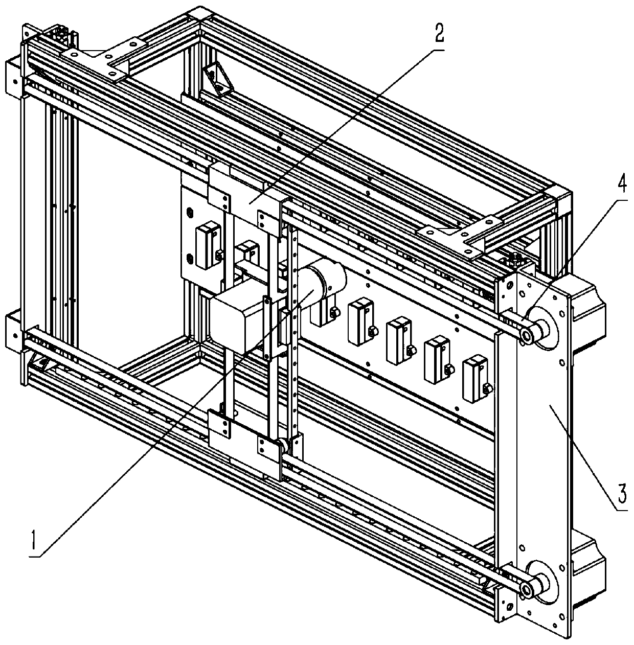
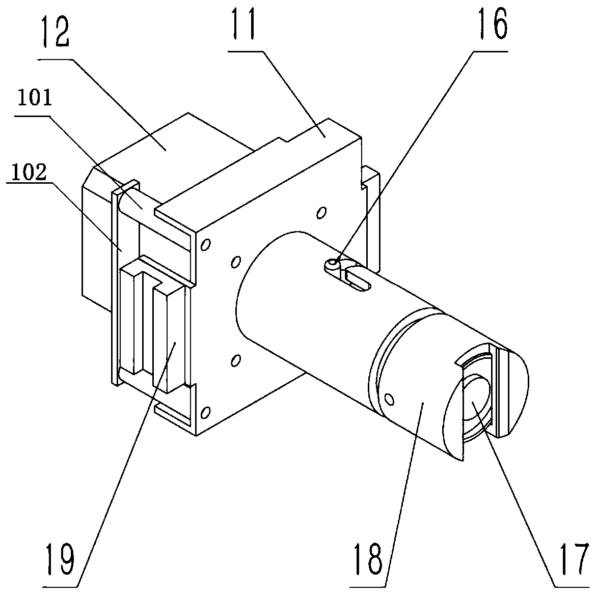
[0053] refer to Figure 1 to Figure 3 As shown, this embodiment is a pressure plate ejector 1, which includes a base 11, an ejection and retraction drive motor 12, an electromagnet 17 and a transmission assembly, the ejection and retraction drive motor is installed on the base 11, and the electromagnet 17 passes through the transmission assembly. The output shaft of the drive motor 12 is driven and connected by transmission; the base 11 includes a casing extending to the outer periphery of the motor output shaft, and the casing is provided with a guide rail groove;

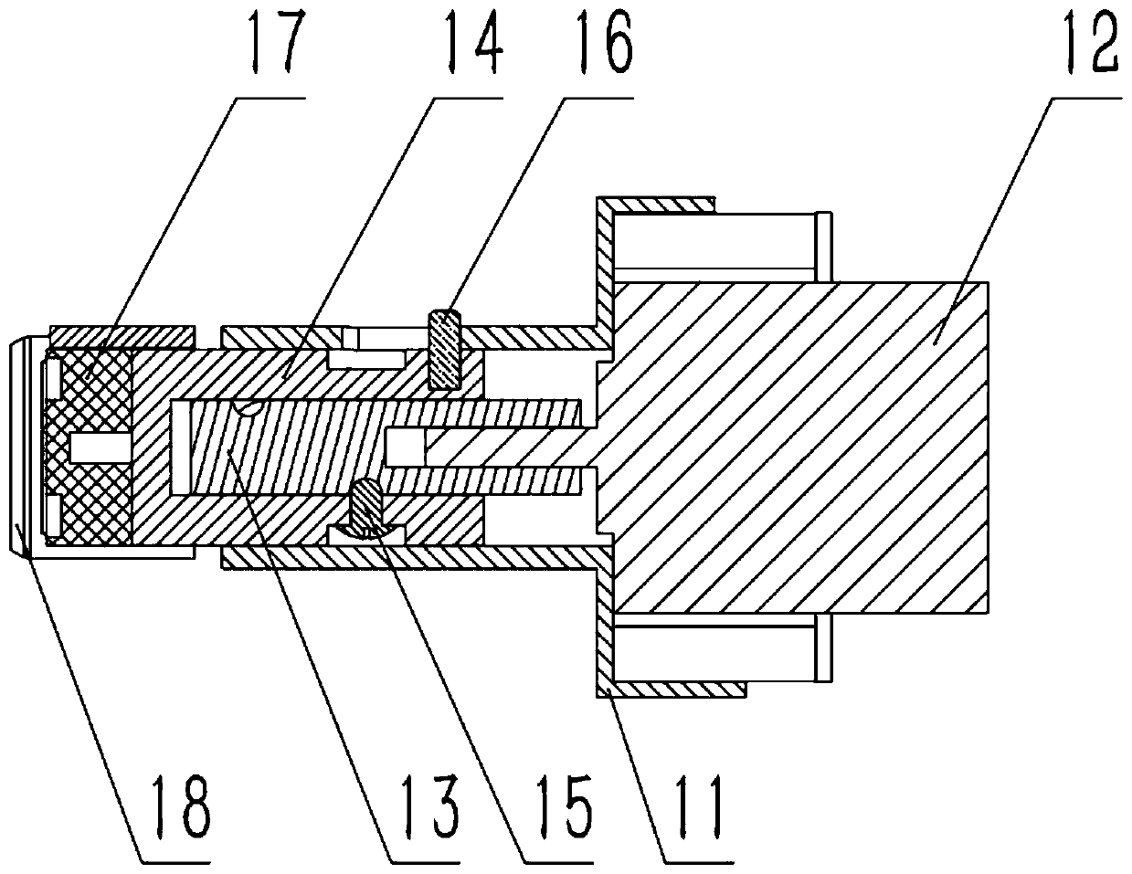
[0054] The transmission assembly includes a piston 14. One end of the piston 14 is rotatably connected to the output shaft of the throwing and retracting drive motor, and the other end is fixedly connected to the electromagnet 17. The piston 14 is fixed with a guide pin 16 that can move along the guide rail groove, and the piston 14 passes through the guide pin 16. Slide to connect the housing.

[0055] When the ...

Embodiment 1-1

[0057] Based on Embodiment 1, in this embodiment:

[0058] The transmission assembly also includes a threaded rod 13 with an external thread, and one end of the threaded rod 13 is fixedly connected to the output shaft of the driving motor 12 for throwing and retracting; the piston 14 is hollow and has an open end, and the inner part of the piston 14 is provided with an external thread to match the external thread of the threaded rod. The threaded pin 15 is provided, so that the rotation of the threaded rod 13 can drive the piston 14 to rotate or move in the axial direction in a state where the circumferential movement is restricted. The output shaft of the throwing and retracting drive motor forms a worm drive structure between the threaded rod and the piston, so that the rotation of the motor output shaft can be converted into the axial linear movement of the piston or follow the rotation in the state of unrestricted outer circumference.

[0059] The threaded rod 13 , the pis...

Embodiment 2

[0066] Based on Example 1, combined with Figure 1 to Figure 5 ,in particular figure 1 , this embodiment is a pressure plate throwing and retracting mechanism based on the pressure plate throwing and retracting device in the first embodiment, including a frame 3, a pressure plate throwing and withdrawing device 1 and a mobile driving unit for the throwing and withdrawing device; any one of the embodiments; the ejector mobile drive unit includes a mobile drive motor, a transmission timing belt 4 and a mobile pair 2;

[0067] refer to Figure 5 As shown, there are at least two mobile drive motors, which are respectively installed on both sides of the frame 3 or both ends on the same side, and an output synchronizing wheel 36 is installed on the output shaft. The four corners of the frame are not installed to move The corners of the driving motor are respectively installed with frame synchronizing wheels 37;

[0068] The frame is provided with at least one linear transverse gu...


PUM


Abstract

The invention discloses a pressing plate throwing and withdrawing device, an automatic pressing plate throwing and withdrawing mechanism and a pressing plate throwing and withdrawing control system. In the pressing plate throwing and withdrawing device, an electromagnet is in transmission connection with an output shaft of a throwing and withdrawing driving motor through a transmission assembly. In the pressing plate throwing and withdrawing mechanism, a throwing and withdrawing device moving driving unit comprises a moving driving motor, a transmission synchronous belt and a moving pair; thetransmission synchronous belt forms an I-shaped path in the moving plane of the pressing plate throwing and withdrawing device, and the transmission synchronous belt is driven to rotate by the rotation of the moving driving motor, so that the pressing plate throwing and withdrawing device can be driven to move to a specified position in the plane. The pressing plate throwing and withdrawing control system comprises a data processor and an action controller. The data processor receives an external pressing plate operation instruction and then converts the instruction into the number of revolutions and the direction of the driving motor, then the action controller controls the moving driving motor to enable the pressing plate throwing and withdrawing device to move to the designated pressingplate position, and then the throwing and withdrawing driving motor and the electromagnet are controlled to be powered on to complete pressing plate throwing and withdrawing operation. The method canbe suitable for automatic throwing and withdrawing of the pressing plate in relay protection, and a basis is provided for unmanned operation of secondary equipment.

Description

technical field [0001] The invention relates to the technical field of operation and maintenance of substations, in particular to a press plate throwing and withdrawing device, a press plate throwing and withdrawing mechanism, and a press plate throwing and withdrawing control system. Background technique [0002] At present, there are the following two ways to realize the switching of the relay protection pressure plate: the electric pressure plate switching and the traditional soft and hard pressure plate switching. [0003] First, the electric press plate is a new type of press plate throwing and withdrawing method. According to the throwing and withdrawing instructions, the motor or push-pull electromagnet is used as the power source to drive the press plate through a specific mechanical structure. It is characterized in that each press plate will be equipped with A motor or electromagnet. If the number of pressure plates in the screen cabinet is too large, its producti...

Claims


Application Information

Patent Timeline
IPC IPC(8): H02B3/00H02B1/00H02B1/24H02K7/00H02K7/10H02K7/06
CPCH02B1/00H02B1/24H02B3/00H02K7/00H02K7/06H02K7/10H02K7/1004
Inventor 陈纪元俞春林袁涤非孙一昂
Owner NANJING GUODIAN NANZI POWER GRID AUTOMATION CO LTD
Learn More