
Wind driven generator stator iron core lamination forming tool and a lamination forming method

A technology for wind turbines and stator iron cores, which is applied in the direction of manufacturing stator/rotor bodies, etc., can solve the problems of poor alignment of positioning ribs embedded in grooves, difficult separation of positioning support cylinders, etc., to achieve easy on-site operation and improve the quality of lamination welding. , the effect of reducing the probability of scratches

Pending Publication Date: 2020-06-23
CSIC ELECTRICAL MACHINERY SCI & TECH
View PDF0 Cites 5 Cited by
  • Summary
  • Abstract
  • Description
  • Claims
  • Application Information

AI Technical Summary

Problems solved by technology

[0003] The invention provides a wind power generator stator core lamination tooling and a lamination forming method, which solves the difficulty in detaching the integral silicon steel sheet core from the integral positioning support cylinder and stacking in the existing stator core lamination tooling. The technical problem of poor alignment of the positioning rib embedding groove on the silicon steel sheet together

Method used


Image

  • Wind driven generator stator iron core lamination forming tool and a lamination forming method
  • Wind driven generator stator iron core lamination forming tool and a lamination forming method
  • Wind driven generator stator iron core lamination forming tool and a lamination forming method

Examples


Embodiment Construction

[0022] The present invention will be described in detail below in conjunction with the drawings:

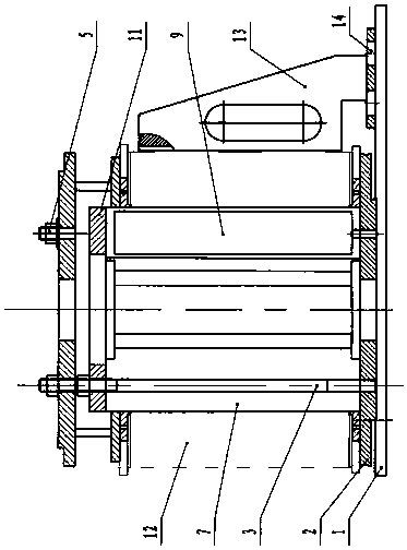
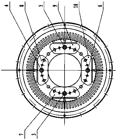
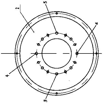
[0023] A wind-power generator stator core laminated molding tooling, comprising a laminated molding operating platform 1 and a stator core silicon steel sheet 12. A stator core laminated base plate 2 is provided on the laminated molding operating platform 1, and the stator iron On the same circumference of the top surface of the core lamination base plate 2, a left positioning lamination screw 3, a rear positioning lamination screw 4, a right positioning lamination screw 5 and a front positioning lamination screw 6 are respectively arranged. The outer circle of 12 is provided with a reinforcing rib embedding groove 20, a left arc-shaped lamination positioning support plate 7 is passed through the left positioning lamination screw 3, and a rear arc lamination is passed through the rear positioning lamination screw 4 Press positioning support plate 8, on the right positioning laminati...


PUM


Abstract

The invention discloses a wind driven generator stator iron core lamination forming tool and a lamination forming method, and solves the problem that an integral silicon steel sheet iron core is difficult to separate from an integral positioning support cylinder in an existing stator iron core lamination tool. An integral positioning support cylinder of a laminated silicon steel sheet iron core isdecomposed into four arc-shaped laminated positioning support plates, a spacing gap is formed between every two adjacent arc-shaped laminated positioning supporting plates, and after stator iron coresilicon steel sheets are laminated, the fixing mechanisms of the arc-shaped laminated positioning supporting plates are dismounted, so that the four arc-shaped laminated positioning supporting platesare in a movable state, and the laminated stator iron core can be conveniently separated from the stator iron core; and the silicon steel sheet excircle positioning vertical plate (13) is matched with a silicon steel sheet laminated excircle positioning groove (21) formed in the excircle of the stator core silicon steel sheet (12), so that the positioning rib embedding grooves in the laminated silicon steel sheets are aligned. The quality of the iron core is improved, and the scratching probability of the inner side wall of the iron core is reduced.

Description

Technical field [0001] The invention relates to a stator iron core lamination forming tool, in particular to a wind generator stator iron core lamination forming tool and a lamination forming method. Background technique [0002] The traditional wind turbine stator iron core is completed on the iron core stacking tooling. The iron core stacking tooling is composed of the stacking tooling base and the integral positioning support cylinder on it; when stacking, the silicon steel sheet Sleeve on the overall positioning support cylinder in turn, and after stacking to a specified height, place a pressure plate and a pressure sleeve on the top silicon steel sheet, press the laminated iron core through the press, and press the outer surface of the iron core The reinforcing ribs on the upper part are embedded in the reserved silicon steel sheet reinforcing ribs embedded in the groove and then welded. The reinforcing ribs connect the laminated silicon steel sheets into a whole. After the ...

Claims


Application Information

Patent Timeline
Patent Type & Authority Applications(China)
IPC IPC(8): H02K15/02
CPCH02K15/02
Inventor 田惠兰张宏飞张旭伍宇红张亚鸽王月刚李华芳
Owner CSIC ELECTRICAL MACHINERY SCI & TECH
Learn More