Efficient double-inlet channel rotational flow atomization desulfurization nozzle

A technology of inlet channels and desulfurization nozzles, which is applied in the field of high-efficiency double inlet channel swirling atomization desulfurization nozzles, can solve the problems of reducing the effective reaction probability of flue gas and slurry, increasing desulfurization energy consumption, and large spray particle size, etc., to achieve improved Atomization effect and desulfurization efficiency, good spatial distribution uniformity, and improved flow resistance

Pending Publication Date: 2020-06-26
HUANENG POWER INT INC +2
View PDF0 Cites 3 Cited by
  • Summary
  • Abstract
  • Description
  • Claims
  • Application Information

AI Technical Summary

Problems solved by technology

In the process of slurry outflow, there are areas with large flow resistance, difficulty in outflow, and small spray flow rate, resulting in uneven spatial distribution of spray flow rate
In the slurry spraying area of ​​the desulfurization tower, the flue gas and the slurry spray flow in the opposite direction. When the slurry spray flow rate is small in some positions, the flue gas is easier to pass through, resulting in the formation of a flue gas corridor and reducing the effective reaction probability of the flue gas and the slurry. cause desulfurization efficiency to decrease
At the same time, this type of nozzle also has the problem of large spray particle size.
The larger the spray particle size of the same slurry, the smaller the specific surface area, and the slower reaction between the slurry and the flue gas will also affect the desulfurization efficiency and increase the desulfurization energy consumption

Method used


Image

  • Efficient double-inlet channel rotational flow atomization desulfurization nozzle
  • Efficient double-inlet channel rotational flow atomization desulfurization nozzle
  • Efficient double-inlet channel rotational flow atomization desulfurization nozzle

Examples


Embodiment Construction

[0019] The present invention is described in further detail below in conjunction with accompanying drawing:

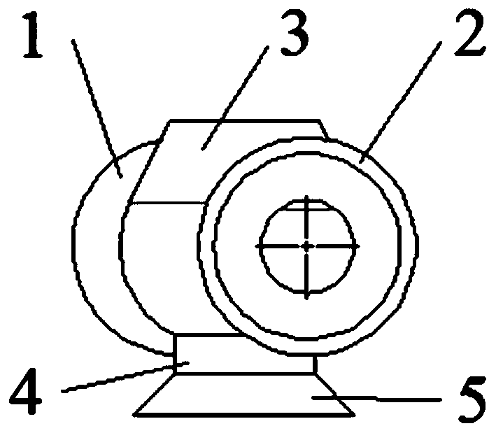
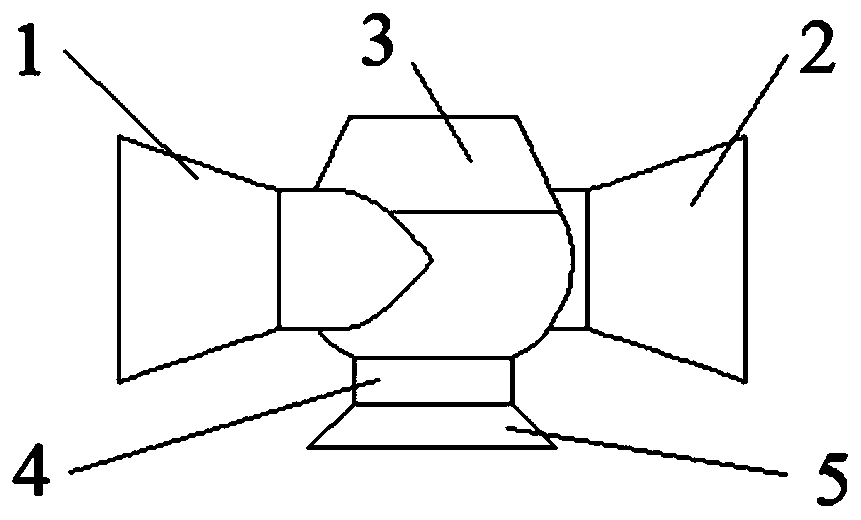
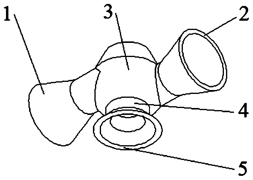
[0020] refer to figure 1 , figure 2 and image 3 , the high-efficiency double inlet channel swirl atomization desulfurization nozzle of the present invention includes a swirl chamber 3, a first inlet channel 1, a second inlet channel 2, an outlet straight pipe section 4 and an outlet flaring section 5, wherein the first The inlet channel 1 is connected with the left inlet of the cyclone chamber 3, the second inlet channel 2 is connected with the right inlet of the cyclone chamber 3, and the upper end of the outlet straight pipe section 4 is connected with the bottom outlet of the cyclone chamber 3 The lower end of the outlet straight pipe section 4 communicates with the outlet flaring section 5; the inner wall of the front side of the first inlet channel 1 is tangent to the inner wall of the front side of the swirl chamber 3, and the inner wall of the second inlet c...


PUM


Abstract

The invention discloses an efficient double-inlet channel rotational flow atomization desulfurization nozzle. A first inlet channel is communicated with a left side inlet of a rotational flow cavity,a second inlet channel is communicated with a right side inlet of the rotational flow cavity, the upper end of an outlet straight pipe section is communicated with a bottom outlet of the rotational flow cavity, and the lower end of the outlet straight pipe section is communicated with an outlet flaring section; the inner wall of a front side surface of the first inlet channel is tangent to the inner wall of a front side surface of the rotational flow cavity; the inner wall of a rear side surface of the second inlet channel is tangent to the inner wall of the rear side surface of the rotationalflow cavity; the axial line of the outlet straight pipe section, the axial line of the outlet flaring section and the axial line of the rotational flow cavity are located on the same straight line. The nozzle can effectively improve the phenomenon that the space flow of a single-inlet channel atomization desulfurization nozzle is not uniform, reduce the atomization particle size, improve the probability that flue gas reacts with liquid drops and improve the desulfurization efficiency of the flue gas.

Description

technical field [0001] The invention belongs to the field of flue gas wet desulfurization, and relates to a high-efficiency dual-entrance channel swirl atomization desulfurization nozzle. Background technique [0002] At present, most of the wet flue gas desulfurization process adopts the limestone-gypsum wet desulfurization process, and the atomizing desulfurization nozzle is the key equipment in the spray absorption tower of the wet desulfurization system. Its main function is to atomize the limestone slurry to provide enough Fine droplets in the contact area, so as to effectively remove SO in the flue gas 2 , the atomization performance of the atomization desulfurization nozzle has a direct impact on the desulfurization efficiency and operating energy consumption of the whole system. [0003] Existing desulfurization system atomization nozzles in the thermal power industry use a large number of single-entrance channel swirl atomization nozzles. The structure of the swirl...

Claims


Application Information

Patent Timeline
Patent Type & Authority Applications(China)
IPC IPC(8): B01D53/78B01D53/50
CPCB01D53/504B01D53/78B01D2258/0283
Inventor 王韶晖石振晶雷鸣牛拥军白少林萧云志何育东王少亮李兴华何仰朋刘海培孟令海余福胜王定帮郭浩然余昭李楠宦宣州吴晓龙
Owner HUANENG POWER INT INC
Why Eureka
Try Eureka