Valve head for pulse solenoid valve

A pulse solenoid valve, valve head technology, applied in the valve operation/release device, valve details, valve device and other directions, can solve the problem of increasing the gap between the moving iron and the static iron core, reducing the stability of the valve head, and unable to close the water flow and other problems, to achieve the effect of improving assembly accuracy, low power consumption, and reducing processing difficulty

Active Publication Date: 2013-06-12
鲍伟军
View PDF1 Cites 0 Cited by
  • Summary
  • Abstract
  • Description
  • Claims
  • Application Information

AI Technical Summary

Problems solved by technology

[0005] 1. When the solenoid valve is in the open state, the moving iron and the static iron core are self-maintained under the magnetic force of the permanent magnet; when the solenoid valve is in the closed state, the moving iron and the static iron core are separated and self-maintained under the elastic force of the spring; When the water pipe vibrates or the water pressure changes too much, the moving iron is easy to attract with the static iron core, and it is easy to stop the water flow; in order to maintain stability, there are usually two methods, one is to strengthen the spring force, and the other is to increase the spring force. The gap between the moving iron and the static iron core requires a greater electromagnetic force to open the solenoid valve, and this needs to be realized by increasing the coil or inputting a larger pulse current. This structure not only consumes power but also requires increase;
[0006] 2. Due to the fixed connection between the moving iron and the sealing fluid head, the stroke of the moving iron will also change under the condition of water pressure changes and aging of the sealing fluid head, which reduces the stability of the valve head

Method used


Image

  • Valve head for pulse solenoid valve
  • Valve head for pulse solenoid valve
  • Valve head for pulse solenoid valve

Examples


Embodiment Construction

[0044] In order to further explain the technical solution of the present invention, the present invention will be described in detail below through specific examples.

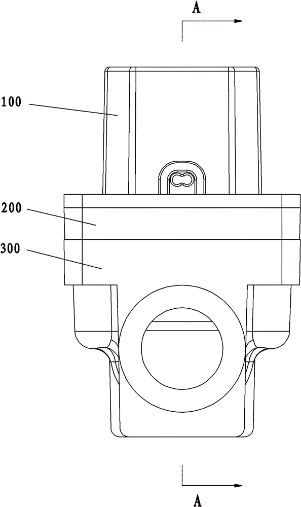
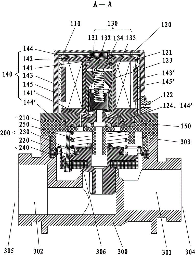
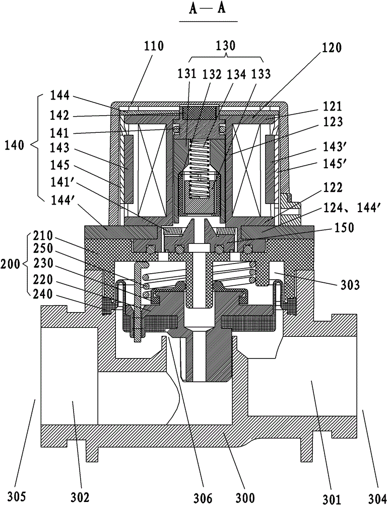
[0045] Such as Figure 1-11 As shown, the valve head 100 of the pulse solenoid valve of the present invention mainly includes a valve cover 110 , a coil bobbin 120 , a moving iron core assembly 130 , a static iron core assembly 140 and a pressure relief nozzle 150 . The valve head 100 is used as the main part of the pulse solenoid valve, and cooperates with the diaphragm assembly 200 and the valve body 300 .

[0046] The valve cover 110 is cap-shaped, with the opening facing downwards. The valve cover 110 is fastened on the lower permeable magnet piece 144' to form a closed space for accommodating the coil bobbin 120 and the moving iron core assembly 130, etc.

[0047] The coil frame 120 is made of a non-conductive and magnetically permeable material, and includes an upper retaining ring 121 , a bobbin 123 and...


PUM


Abstract

The invention discloses a valve head for a pulse solenoid valve. The valve head comprises a coil frame, a static iron core component and a moving iron core component, wherein the coil frame is provided with a through hole which penetrates through the upper and lower surfaces of the coil frame; the static iron core component comprises an upper permanent magnet and an upper static iron core, the upper permanent magnet and the upper static iron core which are mutually sucked are arranged at the upper port of the through hole of the coil frame from top to bottom in sequence; the moving iron core component is flexibly arranged in the through hole on the coil frame in a mode that the upper port of a pressure relief hole on the valve body of the solenoid valve is closed by a moving-down mode and opened by a moving-up mode; the static iron core component also comprises a left permanent magnet and a right permanent magnet; the left permanent magnet and the right permanent magnet are respectively arranged on the left side and right side of the moving iron core component; and the magnetic poles of the left permanent magnet, the right permanent magnet and the permanent magnet are oppositely arranged, and a decompression nozzle is arranged in the through hole of the coil frame. The valve head for the pulse solenoid valve provided by the invention has the advantages that bistable state self-maintenance in the states of opening and closing of the valve head can realized through a magnetic field, thus the stability performance is high.

Description

technical field [0001] The invention relates to a solenoid valve assembly, in particular to a valve head of a pulse solenoid valve. Background technique [0002] Pilot-operated solenoid valves are mainly used in automatic control systems where the medium is water, such as induction sanitary ware, IC water meters, etc. For example, the utility model with the application number 200620010122.X discloses "a miniature high-efficiency DC bistable pulse solenoid valve", which includes a valve body, a valve core assembly and an electromagnet assembly. The valve body is divided into an upper part and a lower part by an intermediate body. The electromagnet assembly is installed on the upper part of the valve body, and the valve core assembly is installed on the lower part of the valve body. The lower part of the valve body is divided into the inlet fluid chamber, the outlet fluid chamber and the valve core chamber by the valve core assembly. The inner cavities of the spool are conne...

Claims


Application Information

Patent Timeline
Patent Type & Authority Patents(China)
IPC IPC(8): F16K31/06
Inventor 鲍伟军
Owner 鲍伟军
Why Eureka
Try Eureka