Uniform distribution method for mold bases, uniform distribution mechanism for mold bases and double-cone channel crimping machine

A crimping machine and mold base technology, which is applied in the field of crimping machines, can solve problems such as uneven width, uneven distribution of mold bases, and affecting crimping quality, so as to improve crimping quality and avoid displacement

Pending Publication Date: 2020-06-26
ZHEJIANG RUICHENG MASCH MFG CO LTD
6 Cites 0 Cited by

AI-Extracted Technical Summary

Problems solved by technology

Due to the uneven distribution of the mold base, the size of the mold base gap at the end of the crimping stroke of the crimping operation is different, and its direct reflection on the crimp...

Method used

[0037] The positioning mechanism 3 is used to control the pressing position of the workpiece. The mechanism includes a stepping motor, a feed screw and a resistance scale, etc., and can automatically adjust the pressing position of the workpiece according to the pressing position information stored in the PLC. The cooling system 4 cools the hydr...

Abstract

The invention discloses a uniform distribution method for mold bases, a uniform distribution mechanism for the mold bases and a double-cone channel crimping machine. According to the uniform distribution method for the mold bases, key slots are formed in a double-cone channel surface of the double-cone channel crimping machine and double-cone surfaces of various lobes of mold bases matched with the double-cone channel surface; limiting and guiding effects are achieved through arranging guide keys in the key slots; and the various lobes of mold bases are uniformly distributed in the peripheraldirection in the crimping work process through cooperation with springs arranged between various lobes of mold bases all the time. The mold bases of the double-cone channel crimping machine can be accurately distributed, and the mold bases are prevented from displacing in cone channels, so that the crimping quality is improved.

Application Domain

Shaping tools

Technology Topic

EngineeringMechanical engineering

Image

  • Uniform distribution method for mold bases, uniform distribution mechanism for mold bases and double-cone channel crimping machine
  • Uniform distribution method for mold bases, uniform distribution mechanism for mold bases and double-cone channel crimping machine
  • Uniform distribution method for mold bases, uniform distribution mechanism for mold bases and double-cone channel crimping machine

Examples

  • Experimental program(1)

Example Embodiment

[0033] In order to make the purposes, technical solutions and advantages of the embodiments of the present invention clearer, the technical solutions in the embodiments of the present invention will be clearly and completely described below with reference to the accompanying drawings in the embodiments of the present invention. Obviously, the described embodiments These are some embodiments of the present invention, but not all embodiments. Based on the embodiments of the present invention, all other embodiments obtained by those of ordinary skill in the art without creative efforts shall fall within the protection scope of the present invention.
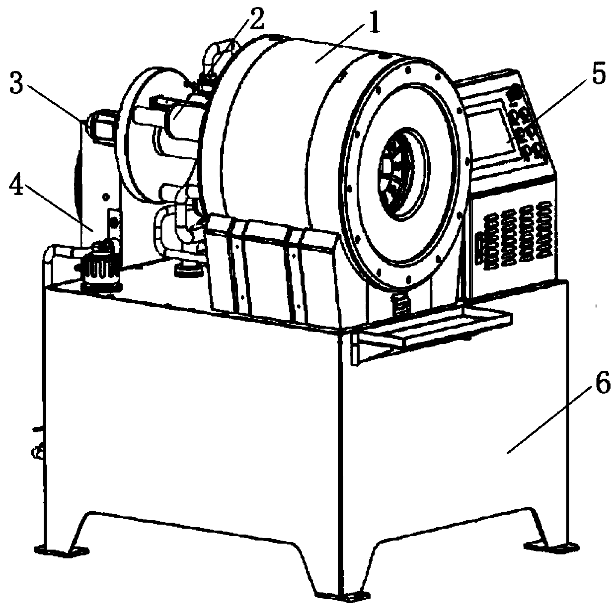
[0034] like figure 1 As shown, a schematic structural diagram of a double-cone crimping machine in the prior art includes a crimping machine main body 1 , a pull-back oil cylinder 2 , a positioning mechanism 3 , a cooling system 4 , an operation panel 5 and a bed 6 .
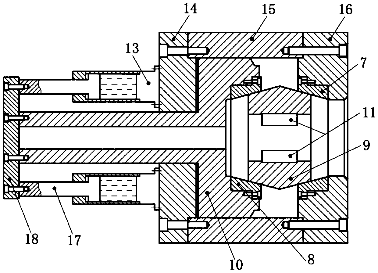
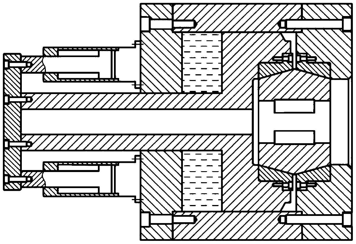
[0035] combine Figure 2 to Figure 4 As shown, the main body 1 of the crimping machine includes a fixed cone 7, a movable cone 8, a die base 9 and a crimping oil cylinder (not shown in the figure). After the hydraulic oil is input from the withholding cylinder, the main piston 10 is pushed forward, and the main piston 10 pushes the movable cone 8 forward. The die base 9 is located between the movable cone 8 and the fixed cone 7, and gradually closes as the distance between the movable cone 8 and the fixed cone 7 decreases, and the inner diameter of the die 11 on the die base 9 also gradually becomes smaller, so that the The workpiece placed in the die 11 is crimped. The pull-back cylinder 2 pulls the movable cone 8 away from the fixed cone 7 . Due to the action of the built-in springs 12 between the mold bases 9, the mold bases 9 are closely attached to the taper channel. Due to the increase of the distance between the movable taper path 8 and the fixed taper path 7, the mold bases 9 are also gradually opened. 11 The inner diameter also gradually becomes larger.
[0036] like figure 2 and image 3As shown in the drawing, the principle in the pullback limit state and the pressing limit state is described as follows, the front end cover 16 and the rear end cover 14 are fixed on the master cylinder 15 by high-strength bolts, the main piston 10 and the master cylinder 15 , The rear end cover 14 forms a single-acting oil cylinder. After the hydraulic oil is introduced, the piston 10 moves forward and plays the role of withholding. The movable cone 8 is fixed on the main piston 10 by bolts, and follows the main piston 10 to move forward or backward. The fixed cone 7 is fixed on the front end cover 16 by bolts and is stationary. The die base 9 is divided into eight parts, and a spring 12 is installed between the die bases 9, so that the gap between the die bases 9 of each segment is approximately uniform and close to the cone. The die 11 is also divided into eight parts, which are respectively installed on the eight-part mold base 9 . When the movable cone channel 8 is pushed toward the fixed cone channel 7, the distance between the die bases 9 decreases and closes, and the die 11 is closed accordingly. When the movable cone 8 is pulled away from the fixed cone 7, the die base 9 is close to the cone due to the action of the spring 12, so the die base 9 is continuously opened, and the die 11 is also opened. The pull-back cylinder block 13 is mounted on the rear end cover 14 , and the pull-back cylinder piston rod 17 is connected to the main piston 10 through a connecting plate 18 . When the hydraulic oil is fed into the pull-back cylinder, the piston rod 17 of the pull-back cylinder retreats in a direction away from the rear end cover 14 , and the main piston 10 is driven to retreat through the connecting plate 18 . As the main piston 10 and the movable cone 8 are pulled away from the fixed cone 7, the die base 9 and the die 11 are opened accordingly.
[0037] The positioning mechanism 3 is used to control the workpiece pressing position. The mechanism includes a stepper motor, a feed screw, a resistance ruler and other components, and can automatically adjust the workpiece pressing position according to the pressing position information stored in the PLC. The cooling system 4 cools the hydraulic oil heated up for the crimping and pulling back actions. The operation panel 5 is composed of buttons and a human-computer interaction touch screen, which can facilitate human-computer interaction, data input, and collection operations. The bed 6 has an integrated oil tank, and the oil pump is installed under the liquid level of the bed oil tank.
[0038] It can be seen that the distribution of the die base 9 of the prior art crimping machine is completely determined by the spring force of the spring 12. Under the action of the gravity of the die base 9, the spring force on the lower circumference of the die base 9 is slightly larger than the spring force on the upper circumference, so that The mold bases 9 can be roughly evenly distributed, but cannot be precisely distributed. With the accumulation of the number of crimping processes, the springs 12 are constantly tightened and the performance also changes. Moreover, the mold bases 9 themselves may also rotate in the cone, so that the upper and lower circumferences are rotated. The die base 9 is displaced, and the distribution of the die base 9 becomes more and more uncontrollable. Due to the uneven distribution of the die base 9, the size of the die base 9 gap at the end of the crimping operation is different, which is a direct reflection on the crimping workpiece. Due to the different widths of the uplift parts of the crimping parts, the axial bending of the crimping parts and other defects that seriously affect the quality of the crimping.
[0039] In the method for evenly distributing the die bases of the present invention, key grooves are provided on the double cone surface of the double cone road crimping machine and on the double cone surfaces of each lobe die base matched with the double cone road surface. The guide keys are installed to realize the limiting and guiding function, and cooperate with the springs arranged between the mold bases, so that the mold bases are always evenly distributed in the circumferential direction during the crimping process. Specifically, the guide key is fixedly connected with the die base keyway, and the guide key is slidably matched with the taper channel keyway. Further, during the crimping process, when the die on the die base contacts the crimping workpiece and bears the crimping pressure, the side surface of the guide key and the side surface of the tapered keyway keep a gap, so that when the crimping pressure is applied, the When the contact friction is used, the energy consumption caused by the contact friction is avoided, and the problem of the wear of the guide key and the shortening of the life is avoided. see Figure 5 and Image 6 Shown is a schematic diagram of the distribution structure of the mold bases according to the embodiment of the method for evenly distributing the mold bases of the present invention. Since the cooperation between the guide key and the keyway plays a role of limiting and guiding, it can ensure that the mold bases are separated and closed for the withholding operation. During the entire stroke, it is always kept at the same distance and precise distribution in the circumferential direction, which effectively avoids the displacement of the die seat in the cone.
[0040] like Figure 7 to Figure 12 As shown, in the die base uniform distribution mechanism of the embodiment of the present invention, the double-cone channel in the main body of the crimping machine is a movable cone channel 7 and a fixed cone channel 8, and each mold base 9 in the main body of the crimping machine is in the shape of a fan ring and the die base 9 A spring 12 is provided in between. The outer circular arc surface of the die base 9 is formed with a double-cone surface matched with the double-cone surface of the movable cone 8 and the fixed cone 7. The double-cone surface and the double-cone A taper keyway 20 and a die base keyway 21 are respectively provided on the surfaces to match, and a guide key 19 is fixedly mounted on the die base keyway 21 , and the guide key 19 is slidingly matched with the taper keyway 20 .
[0041] Specifically, as Figure 13 As shown, the guide key 19 is divided into a fixed end guide key body 22 and a sliding end guide key body 23 along the height direction, the fixed end guide key body 22 is built in the mold base keyway, the sliding end guide key body 23 The body 23 is slidably fitted with the tapered keyway 20 . Further, the sliding end guide key body 23 includes a wide key portion 24 and a narrow key portion 25 along the length direction, the wide key portion 24 and the narrow key portion 25 smoothly transition, the tapered keyway 20 along The length direction includes a wide keyway portion 26 and a narrow keyway portion 27, the wide keyway portion 26 and the narrow keyway portion 27 transition smoothly between the wide keyway portion 26 and the narrow keyway portion 27, the width of the narrow keyway portion 25 is smaller than the width of the narrow keyway portion 27, so The width of the wide key portion 24 is larger than the width of the narrow key groove portion 27 . Preferably, the width difference between the wide key portion 24 and the narrow key groove portion 27 is 1 mm, so that a 0.5 mm gap is maintained between the side surface of the wide key portion 24 and the corresponding side surface of the narrow key groove portion 27 .
[0042] like Figure 14 As shown, when the die base 9 is in the non-crimping working state, the wide key portion 24 is located in the narrow key groove portion 27, and the side surface of the wide key portion 24 and the side surface of the narrow key groove portion 27 are in contact to maintain a tight fit, It cooperates with the spring 12 to maintain the circumferentially uniform arrangement of the mold bases.
[0043] like Figure 15 As shown in the figure, during the crimping operation, the die base 9 is gradually closed, and when the die comes into contact with the workpiece and bears a slight crimping pressure, the die base 9 stops moving forward with the movable cone 8, and the movable cone 8 guides the key body 23 along the sliding end. Continue to slide and increase the buckle pressure on the die base 9, at this time, the wide key part 24 enters the wide key groove part 26 from the narrow key groove part 27, the sides of the wide key part 24 and the wide key groove part 26. There is a clearance fit between them, which means that the side of the guide key 19 does not contact the side of the tapered keyway 20, and there is no friction between them. When the buckle pressure increases, the maximum friction force can reach about 20% of the buckle pressure. On the one hand, energy is wasted. On the other hand, due to the huge friction force, the life of the guide key 19 and the taper keyway 20 is greatly affected.
[0044] The basic structure of the double-cone crimping machine of the present invention can adopt conventional technology, which will not be repeated here. Specifically, the above-mentioned die base uniform distribution mechanism is adopted.
[0045] The above are only specific embodiments of the present application, but the protection scope of the application is not limited to this. Any person skilled in the art who is familiar with the technical scope disclosed in the present application can easily think of changes or replacements, which should be covered in the within the scope of protection of this application. Therefore, the protection scope of the present application shall be subject to the protection scope of the claims.

PUM

no PUM

Description & Claims & Application Information

We can also present the details of the Description, Claims and Application information to help users get a comprehensive understanding of the technical details of the patent, such as background art, summary of invention, brief description of drawings, description of embodiments, and other original content. On the other hand, users can also determine the specific scope of protection of the technology through the list of claims; as well as understand the changes in the life cycle of the technology with the presentation of the patent timeline. Login to view more.

Similar technology patents

Knee joint orthotics capable of preventing lateral twisting force

ActiveCN108245296Aprevent excessive distortionavoid displacement
Owner:周屹杰

Automatic welding device for steel structure shell

ActiveCN113618289Aavoid displacementImproved stability and precision
Owner:NANTONG XINHUA STEEL STRUCTURE ENG

Refrigerator door body, manufacturing method thereof and refrigerator

PendingCN114719516Aavoid displacementreliable manufacturing
Owner:QINGDAO HAIER REFRIGERATOR CO LTD +1

Barrel-type rib expansion equipment

Owner:河北蓝天汽车消声器有限公司

Classification and recommendation of technical efficacy words

  • avoid displacement

Method for producing crankshaft support

InactiveCN1468674Aavoid displacement
Owner:SUZUKI MOTOR CO LTD

Rotor structure of disc type motor

Owner:SHANGHAI PANGOOD POWER TECH CO LTD

Packaging device for backlight modules

ActiveCN102700838Aavoid displacementEnsure transportation safety
Owner:TCL CHINA STAR OPTOELECTRONICS TECH CO LTD
Why Eureka
Try Eureka