Centering clamping jaw based on gear and rack driving

A technology of rack and pinion and clamping jaws, applied in manufacturing tools, forging/pressing/hammer devices, forging/pressing/hammering machinery, etc. force effect

Inactive Publication Date: 2020-06-26
JARI AUTOMATION CO LTD CHINA
View PDF7 Cites 7 Cited by
  • Summary
  • Abstract
  • Description
  • Claims
  • Application Information

AI Technical Summary

Problems solved by technology

The forging production environment is relatively harsh. The mold of the press needs to be continuously sprayed with release agent to ensure that the product does not stick to the mold. The release agent entering the cylinder will reduce the service life of the cylinder. At the same time, the closer the cylinder is to the high-temperature workpiece, the shorter the service life of the cylinder will reduce

Method used


Image

  • Centering clamping jaw based on gear and rack driving
  • Centering clamping jaw based on gear and rack driving

Examples


Embodiment Construction

[0032] The present invention will be described in further detail below in conjunction with the accompanying drawings.

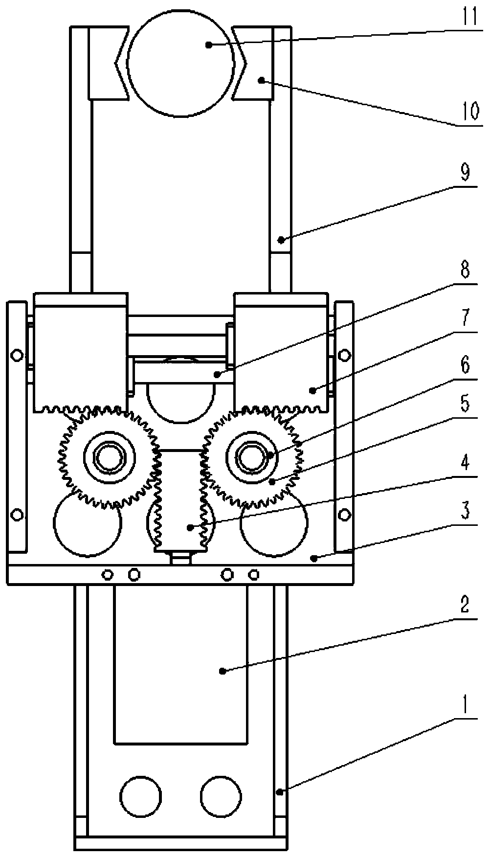
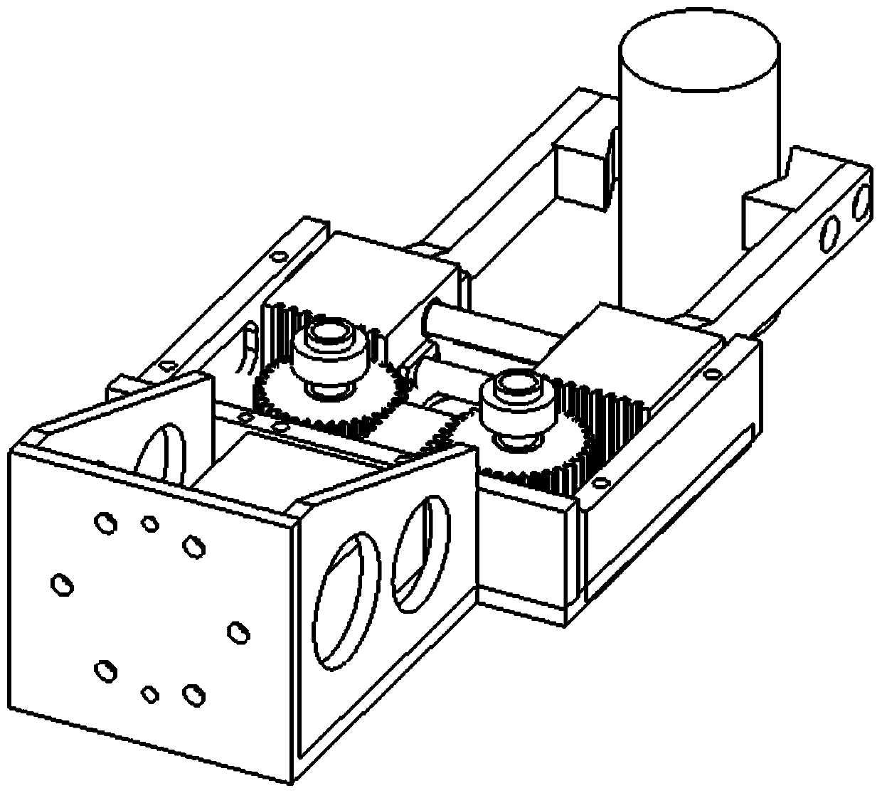
[0033] Such as Figure 1-2 As shown, a centering gripper based on rack and pinion transmission includes robot mounting flange plate 1, cylinder 2, longitudinal rack 4, gear 5, transverse rack 7, guide rod 8, clamping block 9 and V Type positioning block 10;

[0034] The V-shaped positioning block 10 is fixed on the clamping block 9, the clamping block 9 is connected with the transverse rack 7, the transverse rack 7 is set on the guide rod 8, and the transverse rack 7 and the longitudinal rack 4 cooperate with the gear 5 Install, longitudinal rack 4 is connected with cylinder 2.

[0035] When the cylinder 2 is extended, the longitudinal rack 4 moves upwards, driving the gear 5 to rotate, the gear 5 drives the horizontal rack 7 to move, and the two clamping blocks 9 move backwards, and the jaws are in an open state at this time; When the cylinder 2 acts as c...


PUM


Abstract

The invention belongs to the field of automatic forging, and particularly relates to a centering clamping jaw based on gear and rack driving. The centering clamping jaw based on gear and rack drivingcomprises an air cylinder, a guide rod, a bearing, a gear, a longitudinal rack, a transverse rack, clamping blocks and a positioning block, wherein the clamping blocks are connected to the transverserack; the transverse rack is arranged on the guide rod in a sleeving manner; the transverse rack and the longitudinal rack are arranged in cooperation with the gear; and the longitudinal rack is connected to the air cylinder. When the longitudinal rack moves upwards, the gear is driven to rotate, the transverse rack is driven to move by the gear, the two clamping blocks move away from each other in opposite directions, and at the moment, the clamping jaw is in the expansion state. When the longitudinal rack moves downwards, the gear is driven to rotate, the transverse rack is driven to move bythe gear, the two clamping blocks move toward each other in opposite directions, and at the moment, the clamping jaw is in the clamping state. The clamping jaw is used for converting the reciprocating motion of a power mechanism into the reciprocating motion of the clamping blocks through the gear and rack driving; the positioning block is used for ensuring that the center of a clamped workpieceis always in the same position; and the direct effect of the high temperature environment and a release agent on the air cylinder is avoided.

Description

technical field [0001] The invention belongs to the field of six-axis robot automatic forging and forging equipment, and in particular relates to a centering gripper based on rack and pinion transmission. Background technique [0002] The workpiece bar of the forging production line is in a high-temperature state, and then the press is stamped and formed multiple times, and the workpiece needs to be transferred before it becomes the final forged product. The forging production environment is relatively harsh. The mold of the press needs to be continuously sprayed with release agent to ensure that the product does not stick to the mold. The release agent entering the cylinder will reduce the service life of the cylinder. At the same time, the closer the cylinder is to the high-temperature workpiece, the shorter the service life of the cylinder will decrease. [0003] In addition, with the popularization of robotic automated production lines, the product variety of automated ...

Claims


Application Information

Patent Timeline
Patent Type & Authority Applications(China)
IPC IPC(8): B21J13/10
CPCB21J13/10
Inventor 李志新鲁超奇刘志成仲启利陆宗学崔世义韩禄肖广亮刘勇周晓晨
Owner JARI AUTOMATION CO LTD CHINA
Why Eureka
Try Eureka