Spherical magnetic suspension bearing device

A technology of magnetic suspension bearings and magnetic bearings, applied to bearings, shafts and bearings, mechanical equipment, etc., can solve the problems of difficult manufacturing and processing, high power consumption, and no bearing protection, so as to improve service life and precision, reduce Effect of eddy current loss and improvement of reliability

Active Publication Date: 2017-08-18
BEIHANG UNIV
View PDF4 Cites 0 Cited by
  • Summary
  • Abstract
  • Description
  • Claims
  • Application Information

AI Technical Summary

Problems solved by technology

At present, some large-scale spacecraft attitude maneuvering devices are used in spherical magnetic suspension bearing devices. The US Patent No.: No. 4785212, a large-angle magnetic suspension device with a 1988 structure, has the disadvantages of complex structure, difficult manufacturing and processing, and is only used in large-scale Attitude control of spacecraft; U.S. Patent No.: No.6351049,2002 structure of ball-connected magnetic beari

Method used


Image

  • Spherical magnetic suspension bearing device
  • Spherical magnetic suspension bearing device
  • Spherical magnetic suspension bearing device

Examples


Embodiment Construction

[0024] The present invention will be further described below in conjunction with the drawings and specific embodiments.

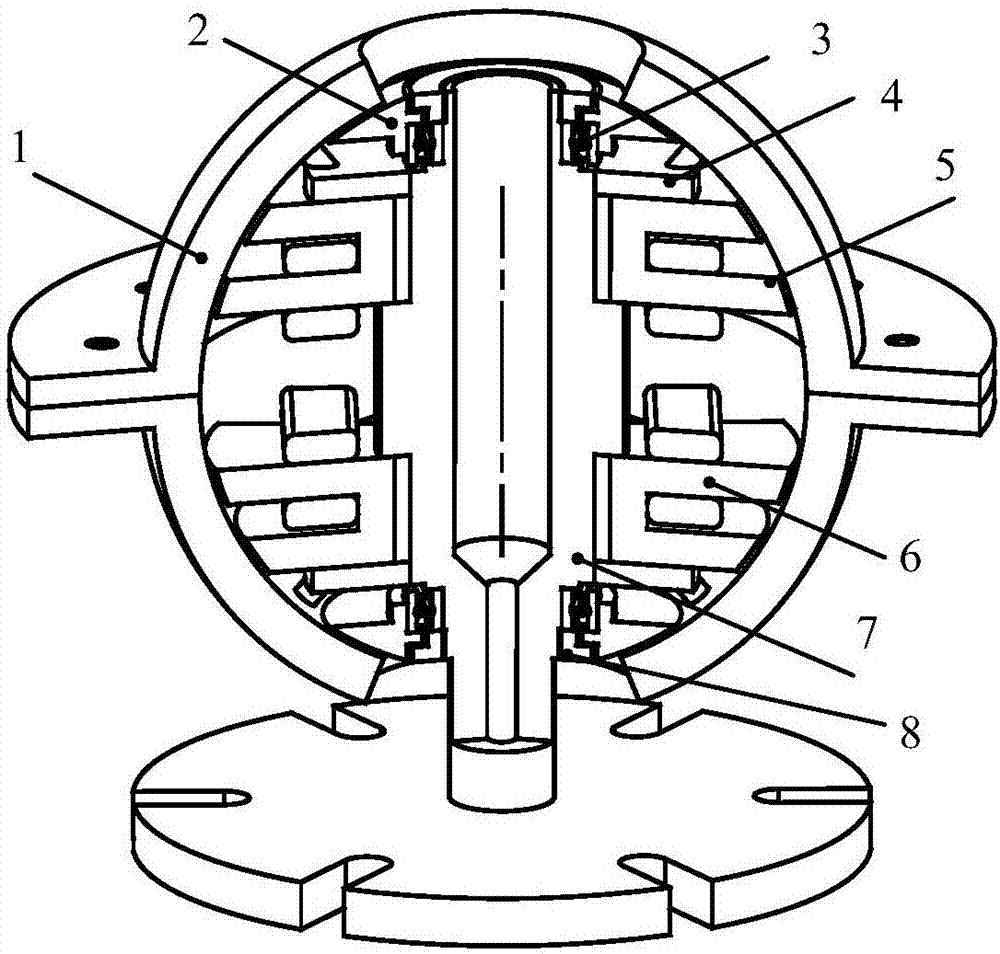
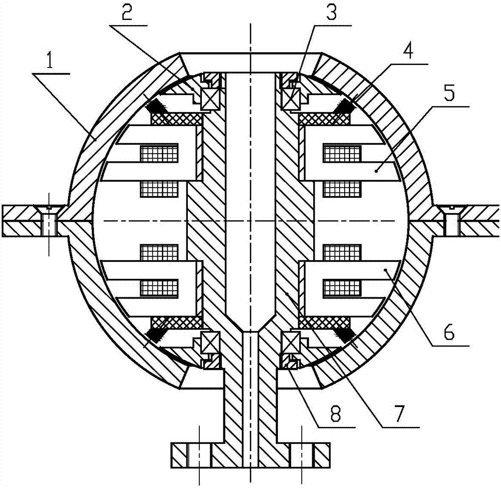
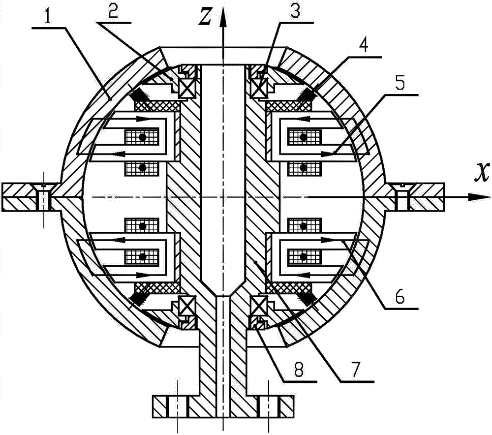
[0025] Such as figure 1 with figure 2 As shown, a spherical magnetic suspension bearing device of the technical solution of the present invention is composed of two parts, stationary and rotating. The stationary part includes the stationary part of the upper magnetic bearing 5, the stationary part of the lower magnetic bearing 6, the auxiliary bearing 3, and the position sensor 4. , Auxiliary bearing seat 2, shaft seat 7 and lock nut 8; the rotating part includes a magnetic suspension rotor 1. The shaft seat 7 is in the middle of the spherical magnetic suspension bearing device. From the middle part of the shaft seat 7 to the outside are the stationary part of the upper magnetic bearing 5, the stationary part of the lower magnetic bearing 6, the position sensor 4, the auxiliary bearing 3 and the lock nut 8. The outer side of the auxiliary bearing 3 is the aux...


PUM


Abstract

The invention discloses a spherical magnetic suspension bearing device which can act as a three-degree-of-freedom non-contact supporting device of systems like a dynamics simulation platform, a three-degree-of-freedom rotary table and a universal momentum wheel. The spherical magnetic suspension bearing device mainly consists of an upper magnetic bearing, a lower magnetic bearing, position sensors, auxiliary bearings, auxiliary bearing pedestals, a magnetic suspension rotor, an axle seat, a lock nut and the like; the axle seat, the upper magnetic bearing, the lower magnetic bearing, the position sensors, the auxiliary bearings and the lock nut are arranged from the center of the spherical magnetic suspension bearing device to the outside sequentially; the auxiliary bearing pedestals are arranged on the outer sides of the auxiliary bearings; the magnetic suspension rotor is located on the outer side of the whole spherical magnetic suspension bearing device; the inner surface of the magnetic suspension rotor, the outer surface of the upper magnetic bearing, the outer surface of the lower magnetic bearing and the surfaces of probes of the position sensors are concentric spherical surfaces; and the center position of the magnetic suspension rotor is kept constant by a control system and the magnetic suspension rotor has three rotational degrees of freedom. The spherical magnetic suspension bearing device has the advantages of wide movement angle range, simple structure, low cost, high reliability and long service life, and the like.

Description

Technical field [0001] The invention relates to the technical field of magnetic suspension bearings, in particular to a spherical magnetic suspension bearing device, which can be used as a multi-freedom non-contact support device for systems such as a space dynamics simulation platform, a three-degree-of-freedom turntable, a robot joint, and a universal momentum wheel. Background technique [0002] Space dynamics simulation platforms, robot joints, three-axis turntables, universal momentum wheels and other devices require multi-degree-of-freedom motion capabilities, in order to reduce the structural complexity, volume and weight of these devices, and improve their service life and reliability (Especially devices that work in a space environment), so there is an urgent need for multi-degree-of-freedom support systems, especially spherical support mechanisms. In addition, the progress of spherical motor technology and its application are also limited by the spherical support techno...

Claims


Application Information

Patent Timeline
IPC IPC(8): F16C32/04
CPCF16C32/0446F16C32/0451F16C32/0485
Inventor 韩邦成李海涛郑世强周新秀乐韵
Owner BEIHANG UNIV
Why Eureka
Try Eureka