
Multifunctional chuck clamp

A multi-functional, chucking technology, used in clamping, manufacturing tools, supports, etc., can solve the problems of time-consuming and laborious, loosening, parts damage, etc., and achieve the effect of avoiding damage

Inactive Publication Date: 2020-06-26
福州约春向科技有限公司
View PDF0 Cites 3 Cited by
  • Summary
  • Abstract
  • Description
  • Claims
  • Application Information

AI Technical Summary

Problems solved by technology

[0002] Fixture refers to the device used to fix the processing object in the process of mechanical manufacturing so that it can occupy the correct position to accept construction or inspection. It is also called fixture. In a broad sense, any process in the process is used to quickly and The device that installs the workpiece conveniently and safely can be called a fixture. There are many types of fixtures, and most of them are fixed and clamped by bolts. However, bolt clamping needs to be manually operated, which may be time-consuming and laborious. And the clamping force The size of the clamp is not well controlled, too much force will easily cause damage to the parts, and if the force is too small, the parts will loosen, and it may also cause damage to the parts during processing. The scope of application of the fixture may also be relatively small. The device that solves the above-mentioned problems

Method used


Image

  • Multifunctional chuck clamp
  • Multifunctional chuck clamp
  • Multifunctional chuck clamp

Examples


Embodiment Construction

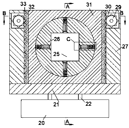
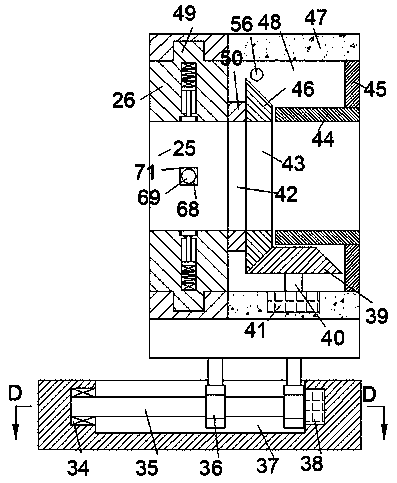
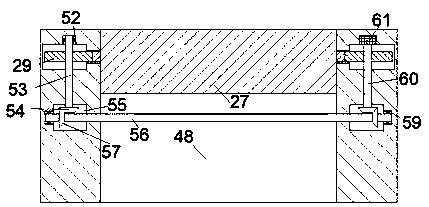
[0016] Combine below Figure 1-5 The present invention is described in detail, and for convenience of description, the orientations mentioned below are now stipulated as follows: figure 1 The up, down, left, right, front and back directions of the projection relationship itself are the same.

[0017] refer to Figure 1-5 , a multifunctional chuck fixture according to an embodiment of the present invention includes a base 20, a support plate 21 is provided on the upper side of the base 20, and a support plate 21 for moving the support plate 21 forward and backward is provided inside the base 20. The moving mechanism 801, the two ends on the upper surface of the support plate 21 are fixed with baffles 27, the block 31 and the first square tube 47 fixed on the front side of the block 31 are arranged between the baffles 27, The opposite side wall of the baffle plate 27 is provided with a tooth chamber 33, and the tooth chamber 33 is provided with a symmetrical rack 32 fixed on t...


PUM


Abstract

The invention discloses a multifunctional chuck clamp. The multifunctional chuck clamp comprises a base, wherein a supporting plate is arranged on the upper side of the base, and a moving mechanism used for moving the supporting plate front and back is arranged inside the base; baffles are fixedly arranged at the two ends of the upper surface of the supporting plate, and a square block and a firstsquare barrel fixedly arranged on the front side of the square block are arranged between the baffles; and a tooth cavity is formed in each of the opposite side walls of the baffles, and racks whichare fixedly arranged on the left surface and the right surface of the square block and are symmetrical left and right in position are arranged in the tooth cavities. A part can be clamped only by controlling the electrifying condition of an electromagnet, compared with a conventional clamp, actual operation is more convenient, and the pressure between a squeezing plate and the part is controlled to be kept at a proper value through a sensor so that the part can be prevented from being damaged by excessive pressure of the squeezing plate.

Description

technical field [0001] The invention relates to the related technical field of clamps, in particular to a multifunctional chuck clamp. Background technique [0002] Fixture refers to the device used to fix the processing object in the process of mechanical manufacturing so that it can occupy the correct position to accept construction or inspection. It is also called fixture. In a broad sense, any process in the process is used to quickly and The device that installs the workpiece conveniently and safely can be called a fixture. There are many types of fixtures, and most of them are fixed and clamped by bolts. However, bolt clamping needs to be manually operated, which may be time-consuming and labor-intensive. And the clamping force The size of the clamp is not well controlled, too much force will easily cause damage to the parts, and if the force is too small, the parts will loosen, and it may also cause damage to the parts during processing. The scope of application of th...

Claims


Application Information

Patent Timeline
Patent Type & Authority Applications(China)
IPC IPC(8): B23Q3/154B23Q1/25
CPCB23Q1/25B23Q3/1543
Inventor 袁婷
Owner 福州约春向科技有限公司
Learn More