Clutch device of fingerprint lock

A technology of clutch device and fingerprint lock, which is applied in the field of locks, can solve problems such as inability to unlock, complex clutch, unfavorable use, etc., and achieve the effects of improving the success rate of unlocking, reducing manufacturing costs, and increasing service life

Pending Publication Date: 2020-06-26
宁波大榭开发区佳洁锌铸件有限公司
View PDF1 Cites 0 Cited by
  • Summary
  • Abstract
  • Description
  • Claims
  • Application Information

AI Technical Summary

Problems solved by technology

[0002] With the continuous development of locks, all kinds of electronic locks have been continuously developed and manufactured, especially electronic locks designed by a combination of wireless remote control, password setting, fingerprint identification, emergency opening, etc. In fingerprint locks, the lock can be opened normally, relying on the lock The clutch inside, the existing clutch is relatively complicated, such as a kind of fingerprint lock with the publication number CN102287090A, which is driven by the motor to move the slider laterally until the marble is pushed into the provocative seat, but this method has high precision requirements for the motor. Higher, it must ensure that the driving force of the motor corresponds to the elastic force of the arc-shaped pressure rod, otherwise it will not be able to unlock, and long-term use will inevitably lead to changes in the elastic force of the arc-shaped pressure rod, so that it cannot be unlocked, which is not conducive to use

Method used


Image

  • Clutch device of fingerprint lock
  • Clutch device of fingerprint lock
  • Clutch device of fingerprint lock

Examples


Embodiment Construction

[0025] The following are specific embodiments of the present invention and in conjunction with the accompanying drawings, the technical solutions of the present invention are further described, but the present invention is not limited to these embodiments.

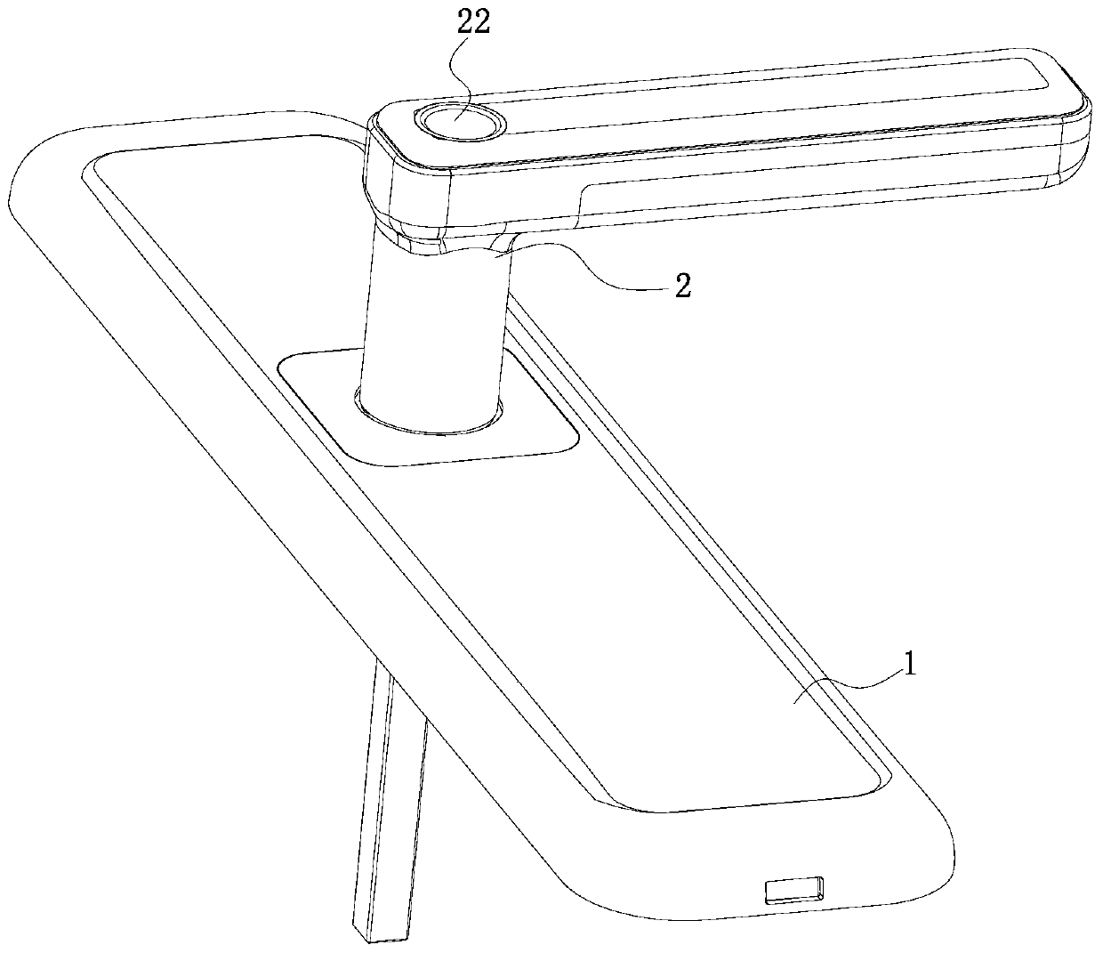
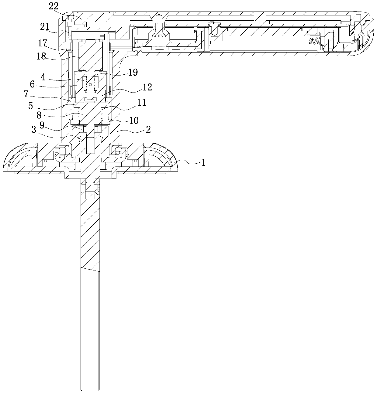
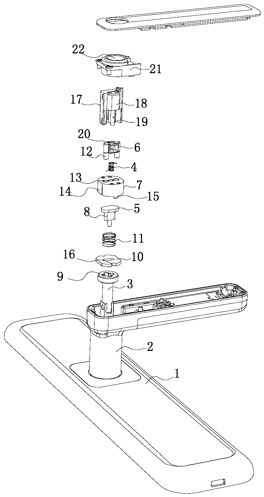
[0026] like Figure 1 to Figure 3 As shown, the clutch device of the fingerprint lock includes: a lock base 1 for installing the lock core, on which the lock base 1 is rotatably connected with a handle 2; The lock cylinder is connected; the driving assembly is fixed vertically in the handle 2; the clutch assembly is vertically arranged in the handle 2, the upper end of the clutch assembly is provided with a clutch spring 4, the clutch spring 4 is connected with the drive assembly, and the lower end of the clutch assembly is arranged There is a transmission block 5; when the drive assembly works, it can drive the clutch spring 4 to compress, and when the clutch spring 4 is compressed, it can drive the transmission block 5 t...


PUM


Abstract

The invention belongs to the field of locks, and provides a clutch device of a fingerprint lock. The clutch device of the fingerprint lock comprises a lock seat for mounting a lock cylinder, a squareshaft connecting block, a driving assembly and a clutch assembly; a handle is rotatably connected to the lock seat, the upper end of the square shaft connecting block is movably inserted into the handle, and the lower end of the square shaft connecting block is connected with the lock cylinder; the driving assembly is vertically and fixedly arranged in the handle; the clutch assembly is verticallyarranged in the handle, a clutch spring is arranged at the upper end of the clutch assembly, the clutch spring is connected with the driving assembly, and a transmission block is arranged at the lower end of the clutch assembly; and when the driving assembly works, the clutch spring can be driven to be compressed, when the clutch spring is compressed, the transmission block can be driven to movedownwards, and the lower end of the transmission block is inserted into the square shaft connecting block. Compared with the prior art, the clutch device has the advantages that a driving motor in theclutch device of the fingerprint lock can drive the transmission block to vertically move downwards until a square shaft is inserted into a square hole, and the clutch function is achieved; and the precision of the driving motor is not controlled, manufacturing cost is reduced, and the service life of the clutch is prolonged.

Description

technical field [0001] The invention belongs to the field of locks, and in particular relates to a clutch device of a fingerprint lock. Background technique [0002] With the continuous development of locks, all kinds of electronic locks have been continuously developed and manufactured, especially electronic locks designed by a combination of wireless remote control, password setting, fingerprint identification, emergency opening, etc. In fingerprint locks, the lock can be opened normally, relying on the lock The clutch inside, the existing clutch is relatively complicated, such as a kind of fingerprint lock with the publication number CN102287090A, which is driven by the motor to move the slider laterally until the marble is pushed into the provocative seat, but this method has high precision requirements for the motor. Higher, it must ensure that the driving force of the motor corresponds to the elastic force of the arc-shaped pressure rod, otherwise it will not be able t...

Claims


Application Information

Patent Timeline
Patent Type & Authority Applications(China)
IPC IPC(8): E05B47/00E05B13/00E05B3/00
CPCE05B47/0012E05B47/068E05B3/00
Inventor 项寅余袁丙仁
Owner 宁波大榭开发区佳洁锌铸件有限公司
Why Eureka
Try Eureka