
Rotary full-view laser radar scanning system

A laser radar and scanning system technology, applied in the field of space measurement, can solve the problems of troublesome point cloud splicing and high R&D cost of single radar

Active Publication Date: 2020-06-26
湖南云箭格纳微信息科技有限公司
View PDF9 Cites 1 Cited by
  • Summary
  • Abstract
  • Description
  • Claims
  • Application Information

AI Technical Summary

Problems solved by technology

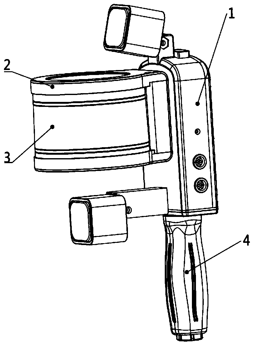
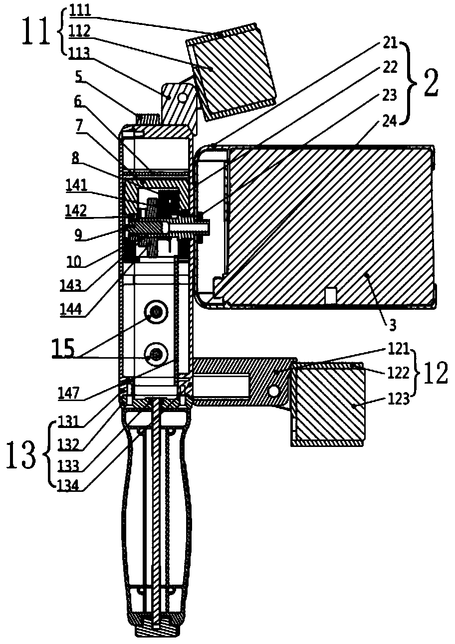
[0003] The invention provides a rotating full-view laser radar scanning system to solve the problems of high R&D cost of single radar and troublesome point cloud splicing in the later stage of multi-site scanning

Method used


Image

  • Rotary full-view laser radar scanning system
  • Rotary full-view laser radar scanning system
  • Rotary full-view laser radar scanning system

Examples


Embodiment Construction

[0027] The specific embodiments of the present invention will be further described below in conjunction with the accompanying drawings. It should be noted here that the descriptions of these embodiments are used to help understand the present invention, but are not intended to limit the present invention. In addition, the technical features involved in the various embodiments of the present invention described below may be combined with each other as long as they do not constitute a conflict with each other.

[0028] Explanation of terms: "full field of view", the field of view is the range that the lidar can scan to the angle. Taking the traditional 16-line 3D lidar as an example, its scanning range is 360° in the horizontal direction of the radar and 30° in the vertical direction. Other lidars, such as solid-state lidars, have a smaller field of view, less than 180° horizontally and vertically. Compared with this type of scanning equipment, the field of view of the present...


PUM


Abstract

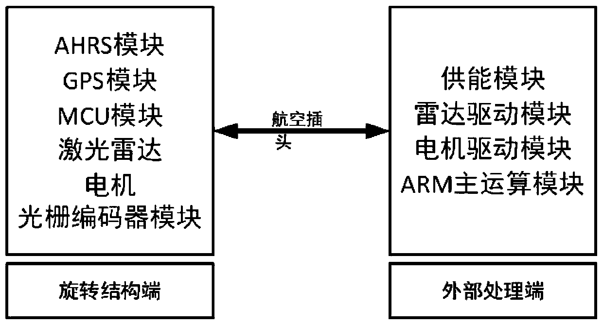
The invention discloses a rotary full-view laser radar scanning system which comprises an AHRS module, a GPS module, an MCU module, laser radar, a motor and a grating encoder module which are installed at the end of a rotary structure. The system further comprises an energy supply module, a radar driving module, a motor driving module and an ARM main operation module. The energy supply module is connected with the MCU module, the ARM main operation module, the motor driving module and the radar driving module. The MCU module is connected with the grating encoder module, the AHRS module, the GPS module and the motor driving module. The motor driving module is connected with the motor; the radar driving module is connected with the laser radar; and the ARM main operation module is connectedwith the motor driving module, the radar driving module, the MCU module and the motor. According to the system, laser point cloud data acquisition of a whole three-dimensional space is effectively completed in a single-point static state.

Description

technical field [0001] The invention relates to the technical field of space measurement, in particular to a rotating full-view laser radar scanning system. Background technique [0002] Lidar is an important device for surveying and mapping. In the fields of architectural modeling, building space measurement, mine monitoring, tunnel monitoring, industrial pipeline monitoring, etc., it is often necessary to measure space with a large field of view and high density. At present, the main equipment on the market to achieve this goal is the ground laser scanner, but limited by the sampling field of view of the equipment, even in the case of no occlusion, the scanner needs to adjust the scanning pose multiple times and perform point cloud stitching in the later stage to obtain a full field of view. point cloud. The single-line laser rotation structure or multi-3D laser radar combination is the main technology used in the above fields. The single-line rotation is limited by the ...

Claims


Application Information

Patent Timeline
Patent Type & Authority Applications(China)
IPC IPC(8): G01S17/89G01S17/86G01S7/481G01S7/497
CPCG01S17/89G01S7/4817G01S7/4811G01S7/4813G01S7/497Y02A90/10
Inventor 高峰李杨寰郭超罗小勇胡骏米鹏
Owner 湖南云箭格纳微信息科技有限公司
Learn More