Control method and control system of PTC heating device
A technology of heating device and control method, applied in auxiliary controller with auxiliary heating device, temperature control by electric method, etc., can solve the problems of poor stability, fluctuation of working current of control system, impact of PTC heating device, etc.
- Summary
- Abstract
- Description
- Claims
- Application Information
AI Technical Summary
Problems solved by technology
Method used
Image
Examples
Embodiment 1
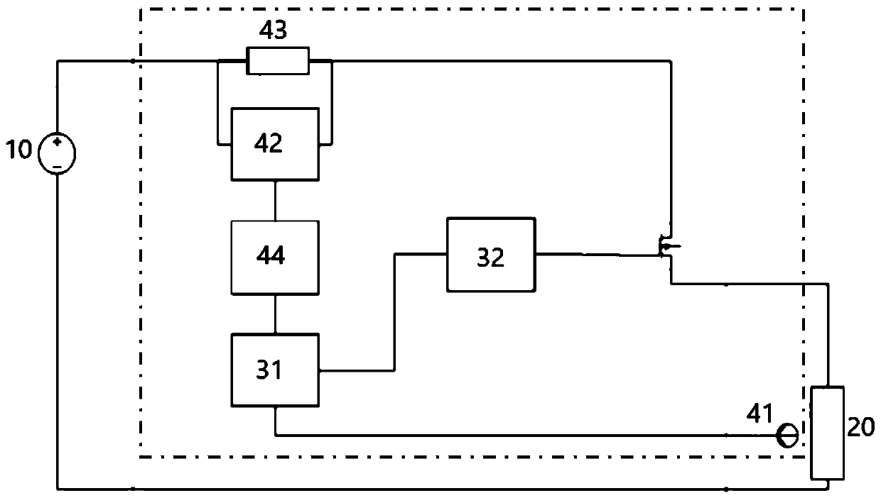
[0047] Example 1: see figure 1 and figure 2 As shown, a control method of a PTC heating device 20 adopts a drive controller 30 electrically connected between the DC bus power supply 10 and the PTC heating device 20 to realize the drive control of the PTC heating device 20; the drive controller The control method includes temperature outer closed-loop control and current inner closed-loop control; wherein, the output signal of the temperature outer closed-loop control is used as the target working current signal input by the current inner closed-loop control, and the output signal of the current inner closed-loop control is used as the PWM control for driving the PTC heating device 20. Air ratio signal; specifically, the temperature outer closed-loop control is based on the temperature difference between the preset target temperature signal and the actual sampling temperature signal, and then the target operating current signal is output after PI or PID adjustment; the current...
Embodiment 2
[0061] Example 2: see Image 6 As shown, a control method for a multi-branch PTC heater 2, the multi-branch PTC heater 2 includes a number of parallel PCT heating devices 20, which are electrically connected between the DC bus power supply 1 and each PCT heating device 20 The driving controller is used to respectively realize the driving control to each PCT heating device 20; the driving controller includes an MCU main control module 31 and several driving circuits 32 for each PCT heating device 20 respectively, and the MCU main control module 31 provides to each PCT heating device 20 respectively. Each drive circuit 32 sends PWM duty cycle signals with equal frequencies, wherein the PWM duty cycle signals of at least two drive circuits 32 have a phase difference not equal to 0, which is used to improve the multi-branch PTC heater 2 in a single signal period. The average degree of internal input power; under the action of this technical idea, the current fluctuation range of t...
Embodiment 3
[0069] Embodiment 3: The remaining technical solutions of this embodiment 3 are the same as those of embodiment 2, the only difference being that the duty cycle ranges of the PWM duty cycle signals PTC1a, PTC2a, and PTC3a in this embodiment 3 are greater than 33.3% and less than 66.6% %; see further Figure 9 As shown, the PWM duty cycle signals PTC1a, PTC2a, PTC3a of each PCT heating device 20 in the present embodiment 3 and the working current waveform diagram of the PCT heater 2, it can be clearly seen that the working current of the present embodiment 3 has good stability Waveform, the input power of the multi-branch PTC heater 2 is evenly distributed in a single signal period.
PUM
 Abstract
Description
Claims
Application Information
 - R&D
- Intellectual Property
- Life Sciences
- Materials
- Tech Scout
- Unparalleled Data Quality
- Higher Quality Content
- 60% Fewer Hallucinations
Browse by: Latest US Patents, China's latest patents, Technical Efficacy Thesaurus, Application Domain, Technology Topic, Popular Technical Reports.
© 2025 PatSnap. All rights reserved.Legal|Privacy policy|Modern Slavery Act Transparency Statement|Sitemap|About US| Contact US: help@patsnap.com


