Three-phase line mutual feedback power balance control method

A technology of power balance and control method, applied in the direction of reducing the asymmetry of the polyphase network, eliminating/reducing the asymmetry of the polyphase network, etc., can solve the problems of the three-phase voltage imbalance at the end of the power grid and so on

Active Publication Date: 2020-06-26
INST OF ELECTRICAL ENG CHINESE ACAD OF SCI
View PDF8 Cites 2 Cited by
  • Summary
  • Abstract
  • Description
  • Claims
  • Application Information

AI Technical Summary

Problems solved by technology

[0005] The purpose of this invention is to solve the problem of unbalanced three-phase voltage at the end of the power grid, including micro-grids and independent micro-grids, and propose a three-phase line mutual feed power balance control method

Method used


Image

  • Three-phase line mutual feedback power balance control method
  • Three-phase line mutual feedback power balance control method
  • Three-phase line mutual feedback power balance control method

Examples


Embodiment Construction

[0053] The present invention will be further described below in conjunction with the drawings and specific embodiments.

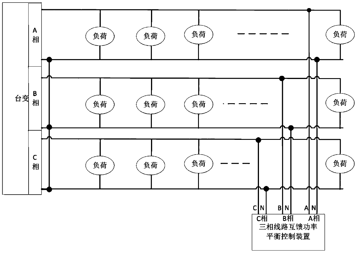
[0054] Such as figure 1 As shown, the present invention reads the electrical parameters of the three-phase line through the three-phase line mutual-fed power balance control device installed at the opposite end of the three-phase line of the power grid, controls the power balance of the three lines, and realizes the three-phase line mutual-fed power at the same time The two-way flow of the power flow achieves the goal of three-phase balance at the end of the grid.

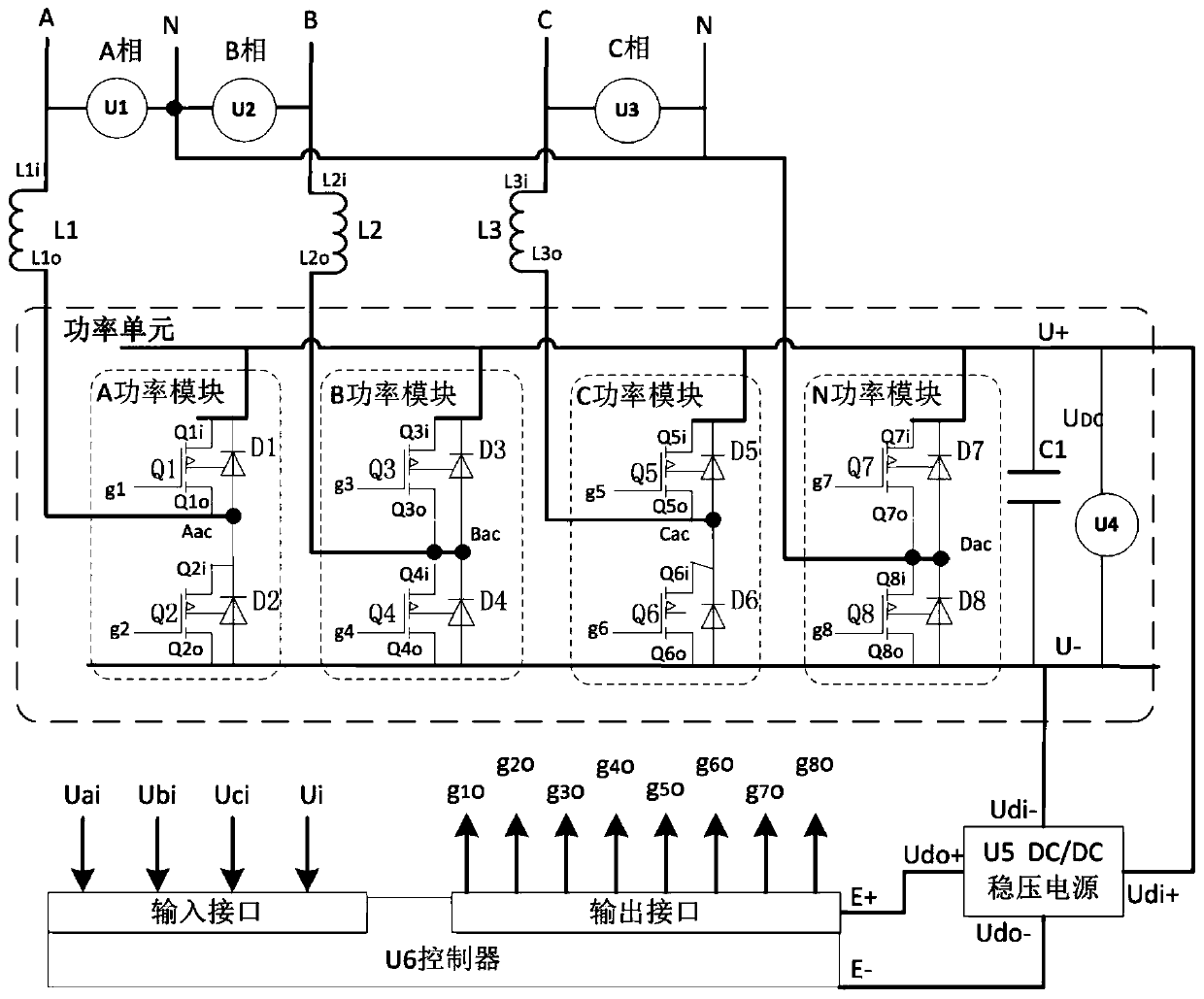
[0055] Such as figure 2 As shown, the three-phase line mutual-fed power balance control device applying the three-phase line mutual-fed power balance control method of the present invention is mainly composed of a power unit, a DC / DC stabilized power supply U5, a controller U6, and an end single-phase power input terminal .

[0056] The power unit is composed of power module A, power module B, power...


PUM


Abstract

A three-phase line mutual feedback power balance control method is provided. By controlling the mutual feedback power of a three-phase line, bidirectional tide flow of the mutual feedback power of thethree-phase line is achieved at the same time, and three-phase balance at the tail end of a power grid is achieved. The method comprises the following steps: 1, respectively comparing three-phase line voltages Ua, Ub and Uc with a national standard voltage lower limit Ulgb and a national standard voltage upper limit Uugb, and identifying a phase line with the highest voltage, a phase line with the second highest voltage and a phase line with the lowest voltage in the three-phase line; meanwhile, calculating the difference value Udiff between the voltage value Uac_max of the highest-voltage phase and the voltage value Uac_min of the lowest-voltage phase; 2, calculating feed power values Pdiff under different conditions according to the impedance rmin of the lowest-voltage phase line and the optimized power coefficient epsilon; and 3, when Ulgb < = (Ua, Ub, Uc) < = Uugb or Uac_max > = Uugb or Uac_min < = Ulgb, controlling the controllable rectification of a power module corresponding tothe highest-voltage phase line, inverting the output of a power module corresponding to the lowest-voltage phase line according to the feed power value, and feeding the power of the highest-voltage phase line to the lowest-voltage phase line to reduce the voltage difference of the lines, wherein Uac_max is the voltage value of the highest-voltage phase line, and Uac_min is the voltage value of the lowest-voltage phase line.

Description

Technical field [0001] The invention relates to a three-phase balance control method at the end of a power grid. Background technique [0002] Because the end users of the power grid use single-phase power supply. As more and more single-phase household appliances, electric processing tools, electric vehicles and other equipment enter the home, the randomness of electricity consumption is often accompanied by an increase in single-phase load, causing the three-phase voltage imbalance in the distribution network to exceed the standard. Seriously, especially in rural areas, the distribution network is basically dominated by single-phase loads, the power supply capacity is weak, the line impedance is large, and the uneven distribution of power loads is particularly prominent. [0003] At present, the rapid development of photovoltaics has caused an explosive growth of distributed photovoltaic power generation in a regional manner. When power is supplied from the power grid, a seriou...

Claims


Application Information

Patent Timeline
Patent Type & Authority Applications(China)
IPC IPC(8): H02J3/26
CPCH02J3/26Y02E40/50
Inventor 王哲赵勇陈伟伟陈卓高娴杨子龙王一波
Owner INST OF ELECTRICAL ENG CHINESE ACAD OF SCI
Why Eureka
Try Eureka