Electronic component, esp. one operating with acoustic surface waves (OFW component)

An electronic device and device technology, applied in the field of electronic devices, can solve the problems of non-sealing, damage, device function damage, etc., and achieve a good sealing effect

Inactive Publication Date: 2003-07-02
EPCOS AG
View PDF2 Cites 0 Cited by
  • Summary
  • Abstract
  • Description
  • Claims
  • Application Information

AI Technical Summary

Problems solved by technology

The problem here, however, is that the electrical connection between the rails on opposite sides of the printed circuit board has to be made through the printed circuit board, so that problems of leaks caused by the housing formed by said components can arise, so for example The function of the device is damaged or destroyed by water vapor

Method used


Image

  • Electronic component, esp. one operating with acoustic surface waves (OFW component)
  • Electronic component, esp. one operating with acoustic surface waves (OFW component)
  • Electronic component, esp. one operating with acoustic surface waves (OFW component)

Examples


Embodiment Construction

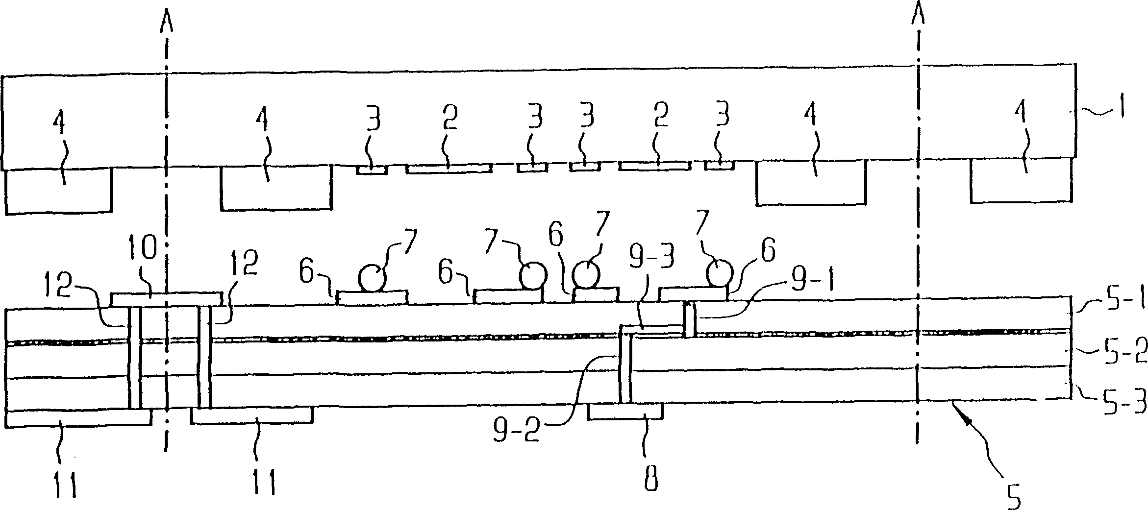
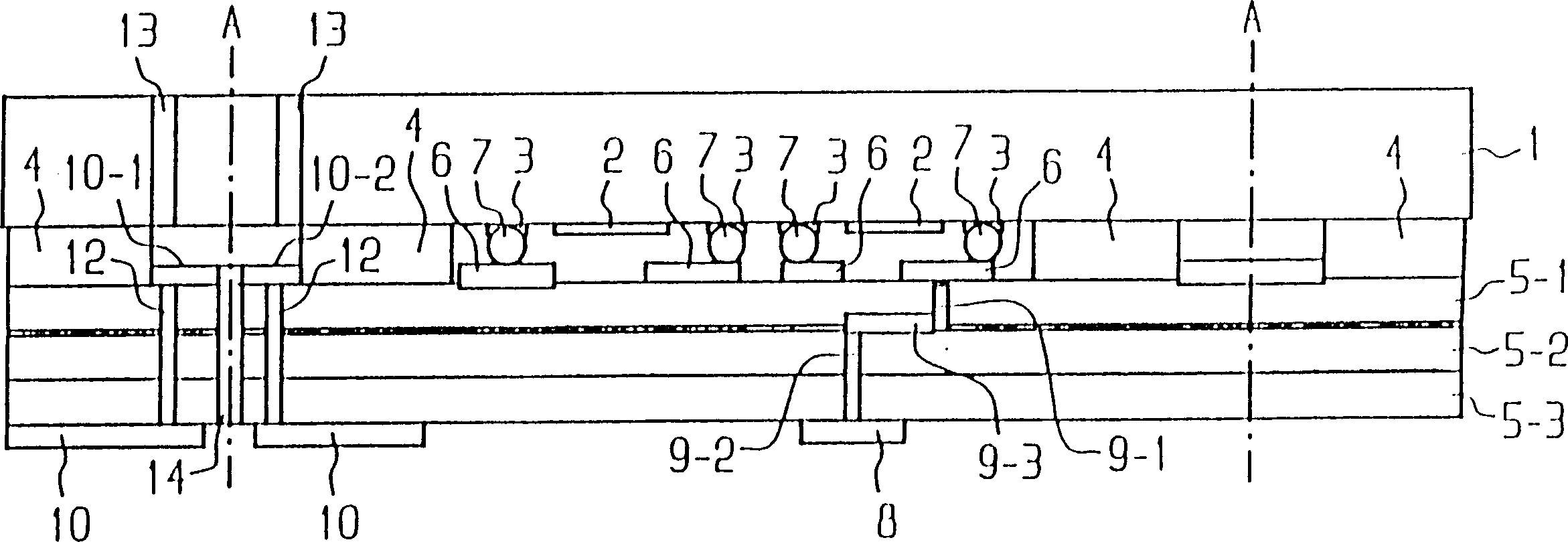
[0020] according to figure 1 The upper part of the OFW device system contains a piezoelectric substrate 1 and the above-mentioned conductive structure 2 , a connection plane 3 - pad - and a frame 4 surrounding the conductive structure 2 and the connection plane 3 . The conductive structure 2 can form, for example, an interdigital transducer, a resonator or a reflector.

[0021] For the sake of clarity, a larger number of device systems in the above-mentioned technologies can be located on one substrate at the same time, in figure 1 The central body 1 is exposed to the left and to the right by a vertical line A, in which a part of the frame 4 is also indicated.

[0022] In addition, there is a printed circuit board 5 on which side rails 6 perpendicular to the component system and contact elements 7 —pumps — are located thereon. In order to indicate a greater number of components, the printed circuit board is extended outwards by a line A.

[0023] device system and printed c...


PUM


Abstract

An OFW component with a component system (1-3) mounted by the flip-chip technique onto a printed circuit board (5) and with a frame (4) surrounding the component structures (1-3), in which conductive tracks (6, 8) are interconnected on the printed circuit board (5) by this through connection (9-1, 9-2, 9-3) in such a way that components (9-1, 9-2) running in the direction of their extension are mutually staggered and interconnected via a connecting member (9-3).

Description

technical field [0001] The above invention relates to electronic devices, especially devices that operate with surface acoustic waves - OFW devices. Background technique [0002] The electronic device of the prior art is advantageous because the base body of the device, the frame between the base body and the printed circuit board surrounding the printed circuit board and the conductive structures already constitute a complete package often referred to as a "chip size package". shell. "Printed circuit board" in the above-mentioned invention is understood to be a support on a plastic and ceramic basis that rises from the guide rails, respectively. The problem here, however, is that the electrical connection between the rails on opposite sides of the printed circuit board has to be made through the printed circuit board, so that problems of leaks caused by the enclosure formed by said components can arise, so for example Water vapor may damage or destroy the function of the ...

Claims


Application Information

Patent Timeline
Patent Type & Authority Patents(China)
IPC IPC(8): H01L23/12H03H9/02H03H9/05H03H9/10H03H9/25
CPCH03H9/059H03H9/05
Inventor W·帕尔A·斯特尔兹尔H·克吕格尔
Owner EPCOS AG
Why Eureka
Try Eureka