3D vision-based method for planning accurate placement trajectory of mechanical arm

A trajectory planning and robotic arm technology, which is applied in the direction of manipulators, program-controlled manipulators, manufacturing tools, etc., can solve the problem that the manipulator cannot place objects at the target point, achieve high precision, improve placement accuracy, and improve accuracy.

Active Publication Date: 2020-06-30
JIHUA LAB
View PDF14 Cites 7 Cited by
  • Summary
  • Abstract
  • Description
  • Claims
  • Application Information

AI Technical Summary

Problems solved by technology
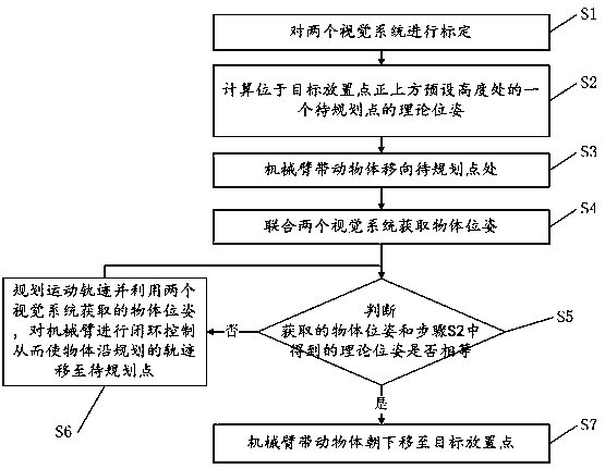
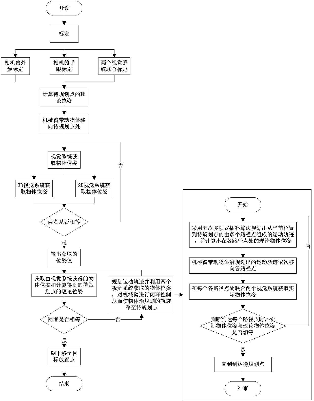
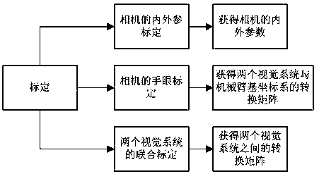
[0007] In view of the shortcomings of the above-mentioned prior art, the purpose of the present invention is to provide a 3D vision-based method for precise placement trajectory planning of a robotic arm, which aims to solve the problem that the current robotic arm cannot accurately place objects at the target point

Method used


Image

  • 3D vision-based method for planning accurate placement trajectory of mechanical arm
  • 3D vision-based method for planning accurate placement trajectory of mechanical arm
  • 3D vision-based method for planning accurate placement trajectory of mechanical arm

Examples


Embodiment Construction

[0071] Embodiments of the present invention are described in detail below, examples of which are shown in the drawings, wherein the same or similar reference numerals denote the same or similar elements or elements having the same or similar functions throughout. The embodiments described below by referring to the figures are exemplary only for explaining the present invention and should not be construed as limiting the present invention.

[0072] In describing the present invention, it should be understood that the terms "center", "longitudinal", "transverse", "length", "width", "thickness", "upper", "lower", "front", " Orientation indicated by rear, left, right, vertical, horizontal, top, bottom, inside, outside, clockwise, counterclockwise, etc. The positional relationship is based on the orientation or positional relationship shown in the drawings, which is only for the convenience of describing the present invention and simplifying the description, rather than indicating ...


PUM


Abstract

The invention provides a 3D vision-based method for planning an accurate placement trajectory of a mechanical arm. The method comprises the steps: S1, calibrating two vision systems; S2, calculating atheoretical pose of a to-be-planned point located at a preset height position directly above a target placement point; S3, driving an object by the mechanical arm to move to the to-be-planned point;S4, combining the two vision systems to obtain an object pose; S5, comparing the obtained object pose with the theoretical pose obtained in the step S2, judging whether the obtained object pose and the theoretical pose are equal or not, and if unequal, executing the step S6, and if equal, executing the step S7; S6, planning a motion trajectory and utilizing the object pose obtained by the two vision systems to perform closed-loop control on the mechanical arm to make the object move to the to-be-planned point along the planned trajectory, and performing the step S5; and S7, driving the objectby the mechanical arm to move down to the target placement point. The method can improve the accuracy of placing the object to the target point by the mechanical arm.

Description

technical field [0001] The invention relates to the technical field of industrial manipulators, in particular to a 3D vision-based trajectory planning method for precise placement of manipulators. Background technique [0002] With the development of industry, the application of robotic arms is becoming more and more common, and the application scenarios of the grasping and placing motion of robotic arms are also becoming more and more extensive. [0003] At present, the methods of grasping and placing objects by the robotic arm include grasping and placing between two points with a preset route, and realizing fast grasping and placing through deep learning; [0004] For the method of grabbing and placing between two points with a preset route, due to long-term reciprocating motion, the movement error of the mechanical arm and the error of the gripper itself will accumulate, resulting in inaccurate placement; [0005] For fast grasping and placing through deep learning, a l...

Claims


Application Information

Patent Timeline
IPC IPC(8): B25J9/16
CPCB25J9/1664B25J9/1697
Inventor 许金鹏温志庆周德成
Owner JIHUA LAB
Why Eureka
Try Eureka