Suspended garbage channel for building construction

A construction and suspension technology, applied in the direction of buildings, building components, building structures, etc., can solve the problems of easy blockage and inconvenient garbage transportation in garbage channels, and achieve the effect of convenient collection, easy transportation and processing, and reduced falling speed.

Inactive Publication Date: 2020-06-30
葛飞月
View PDF9 Cites 0 Cited by
  • Summary
  • Abstract
  • Description
  • Claims
  • Application Information

AI Technical Summary

Problems solved by technology

[0004] Based on the technical problems of inconvenient garbage transportation and easy blockage in the existing garbage channel for building construction, the present invention proposes a suspended garbage channel for building construction

Method used


Image

  • Suspended garbage channel for building construction
  • Suspended garbage channel for building construction
  • Suspended garbage channel for building construction

Examples


Embodiment 1

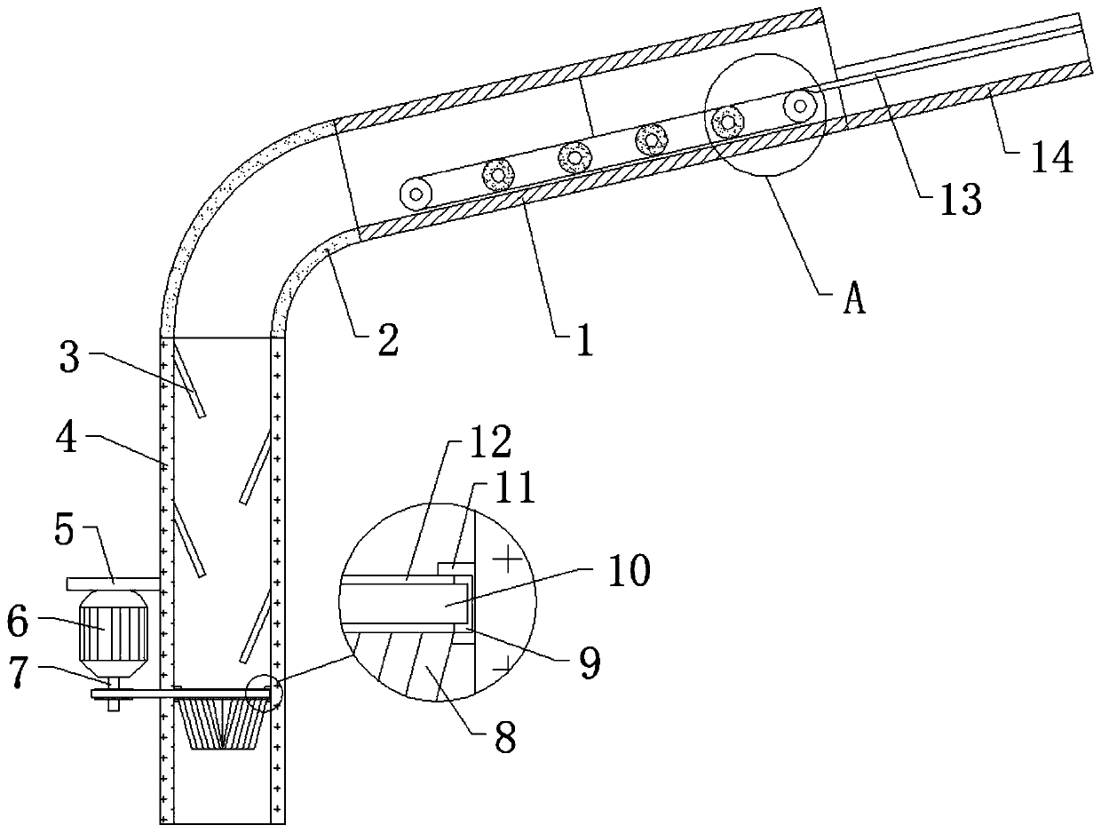
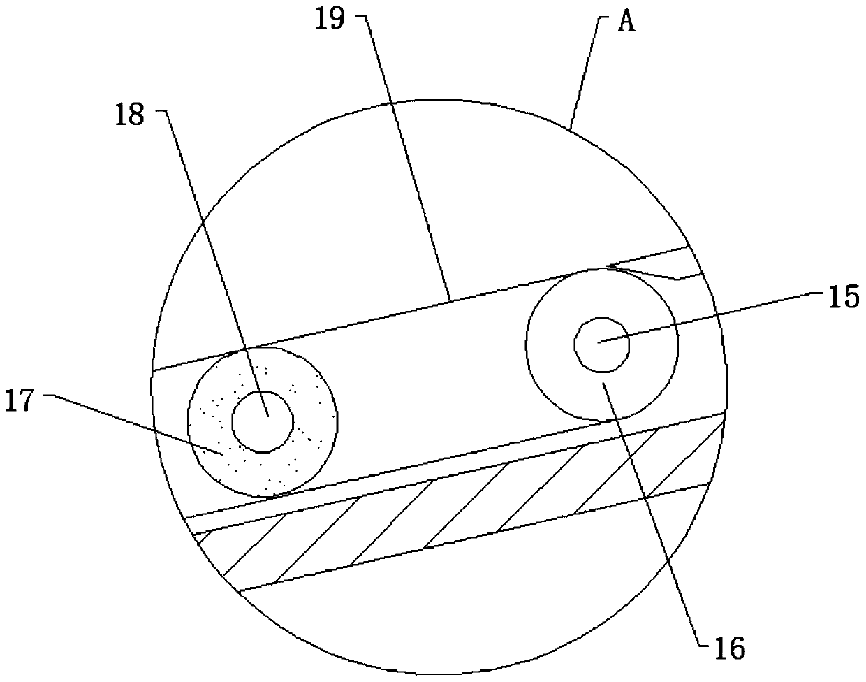
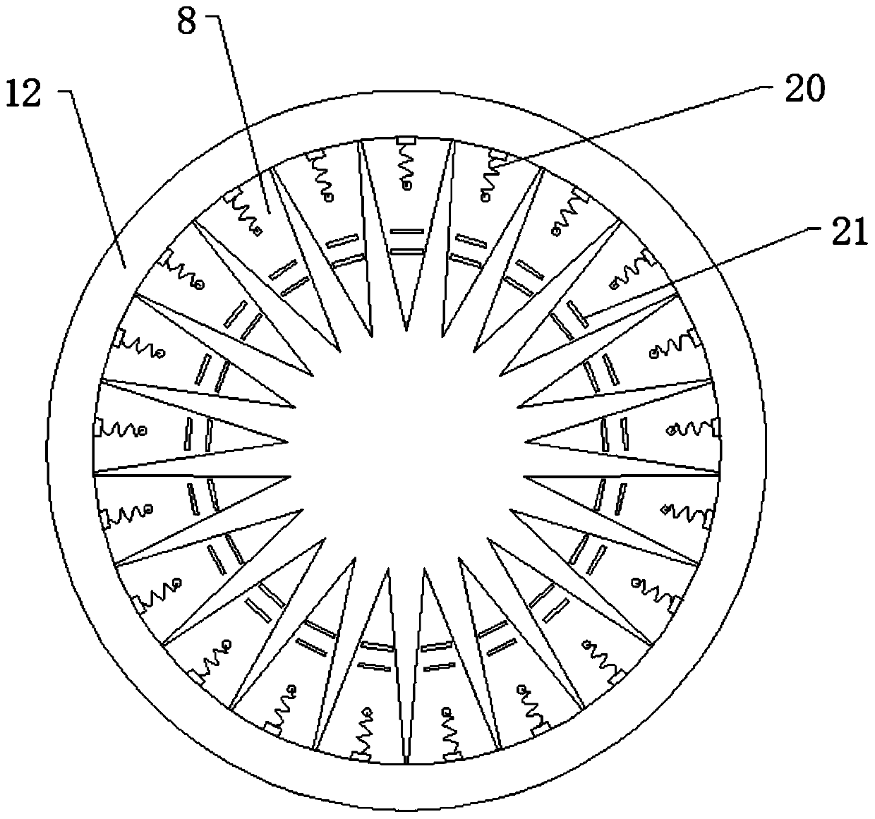
[0027] refer to Figure 1-5 , a suspension type garbage channel for building construction, comprising a first feeding pipe 1, an elbow 2 and a second feeding pipe 4, one end of the elbow 2 is inserted into one end of the first feeding pipe 1, and the elbow 2 The other end of the first feed pipe 1 is inserted into one end of the second feed pipe 4, and the end of the first feed pipe 1 far away from the elbow 2 is welded with a feed trough 14, and a material guide plate 13 is welded on the inner wall of one side of the feed chute 14. The inner wall of the feeding pipe 1 is provided with a conveying mechanism, the surface of the conveying mechanism and the surface of the material guide plate 13 are on the same straight line, and both sides of the inner wall of the second feeding pipe 4 are fixedly connected with rubber plates 3 which are alternately distributed. Alternately distributed rubber plates 3 can buffer the blanking. Both sides of the inner wall of the second feeding pip...

Embodiment 2

[0036] refer to Image 6 , a suspended garbage channel for building construction. Compared with Embodiment 1, this embodiment also includes a hook 24 and a storage bag 25. The two hooks 24 are fixed on the inner walls of both sides of the second feeding pipe 4 by bolts. At the bottom position, the storage bag 25 is hung on the inner walls of the two hooks 24 .

[0037] During use, the hook 24 in the bottom second feed pipe 4 is hung with a storage bag 25, which can be used to collect the construction waste that is discharged down, so that it can be directly consigned in the later stage, and the construction waste is more efficient.


PUM


Abstract

The invention discloses a suspended garbage channel for building construction. The suspended garbage channel aims at the problem that garbage is inconvenient to transport and blocking is likely to happen. According to the following scheme, the suspended garbage channel comprises a first conveying pipe, a bent pipe and a second conveying pipe. One end of the bent pipe is inserted into one end of the first conveying pipe, and the other end of the bent pipe is inserted into one end of the second conveying pipe. A conveying groove is welded to the end, away from the bent pipe, of the first conveying pipe, and a guide plate is welded to the inner wall of one side of the conveying groove. A conveying mechanism is arranged on the inner wall of the first conveying pipe, and the surface of the conveying mechanism and the surface of the guide plate are located on the same straight line. The two sides of the circumferential inner wall of the second conveying pipe are fixedly connected with alternately distributed rubber plates. According to the suspended garbage channel for building construction, falling materials can be blocked properly, and the falling speed of the falling materials is reduced; cutting tooth sheets are arranged at the bottom of an annular belt, the bottoms of the cutting tooth sheets are closed, and the falling materials are blocked by the cutting tooth sheets in the falling process; and under the gravity of the falling materials, the cutting tooth sheets can be opened, then discharging is carried out, and buffering is achieved again.

Description

technical field [0001] The invention relates to the technical field of building construction, in particular to a suspended garbage channel for building construction. Background technique [0002] Building construction refers to the production activities in the implementation stage of engineering construction. It is the construction process of various buildings. When building houses, a large amount of construction waste will inevitably be generated, and when the construction floor is high, the garbage in the floor cannot be easily moved to The ground, so it is necessary to use the garbage channel for the transportation of garbage, so as to facilitate the cleaning of garbage in the floor. [0003] Most of the existing garbage passages for building construction on the market have the following deficiencies during use: the garbage is not easy to be transported to the ground, and the garbage is easy to cause blockage in the passage, and the existing garbage passages for construct...

Claims


Application Information

Patent Timeline
Patent Type & Authority Applications(China)
IPC IPC(8): E04F17/10E04F17/12E04G21/00B02C18/00B02C18/10
CPCB02C18/0092B02C18/10B02C2201/06E04F17/10E04F17/12E04G21/00
Inventor 葛飞月
Owner 葛飞月
Why Eureka
Try Eureka