Clutch mechanism of electronic lock cylinder

A clutch mechanism, electronic lock technology, applied in building locks, building structures, non-mechanical transmission-operated locks, etc., can solve the problems of waste of resources, cumbersome door closing, inconvenient operation, etc., to ensure the effectiveness of use, The effect of improving safety and simple structure

Active Publication Date: 2020-06-30
浙江科利智能科技有限公司
View PDF6 Cites 0 Cited by
  • Summary
  • Abstract
  • Description
  • Claims
  • Application Information

AI Technical Summary

Problems solved by technology

[0003] The Chinese patent with the notification number CN201821116556.7 discloses a clutch mechanism for an electronic lock cylinder, which includes a front handle assembly, a rear handle assembly, and a lock cylinder housing. The front handle assembly includes a front handle, a front main shaft and a The clutch mechanism in the front main shaft and relative to it can move axially. The rear handle assembly includes a rear handle and a rear main shaft. The rear main shaft is sleeved on the front main shaft. At least one communicating In the through hole between the clutch mechanism and the inner wall of the rear main shaft, a clutch part is provided in the through hole, and a snap notch corresponding to the clutch part is provided on the inner wall of the rear main shaft. When the clutch mechanism moves in the axial direction, the clutch part can be driven to The movement on the outside

Method used


Image

  • Clutch mechanism of electronic lock cylinder
  • Clutch mechanism of electronic lock cylinder
  • Clutch mechanism of electronic lock cylinder

Examples


Example Embodiment

[0025] The present invention will be described in further detail below in conjunction with the accompanying drawings.

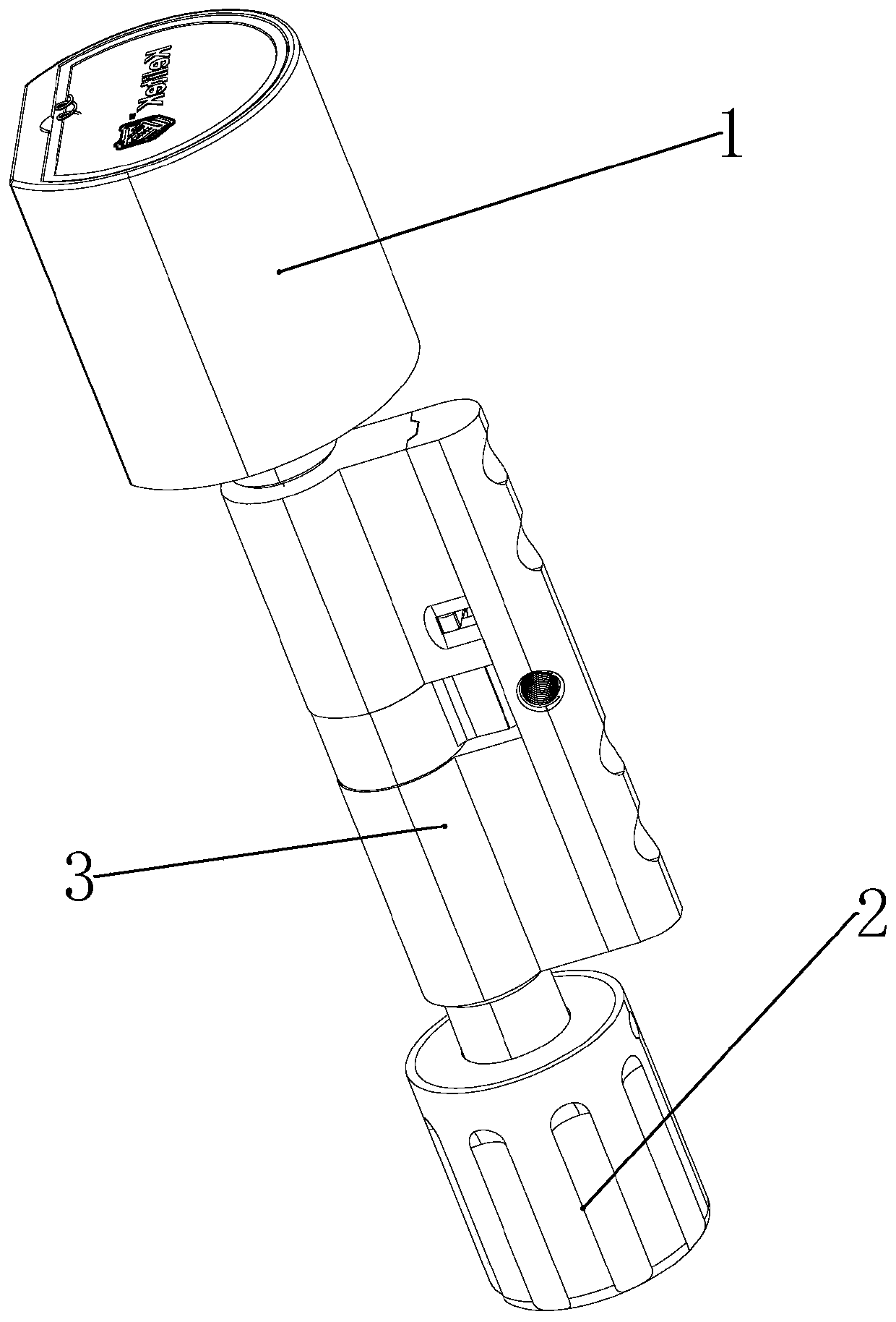
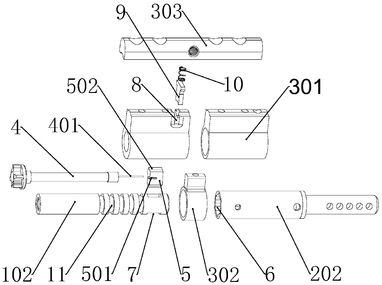
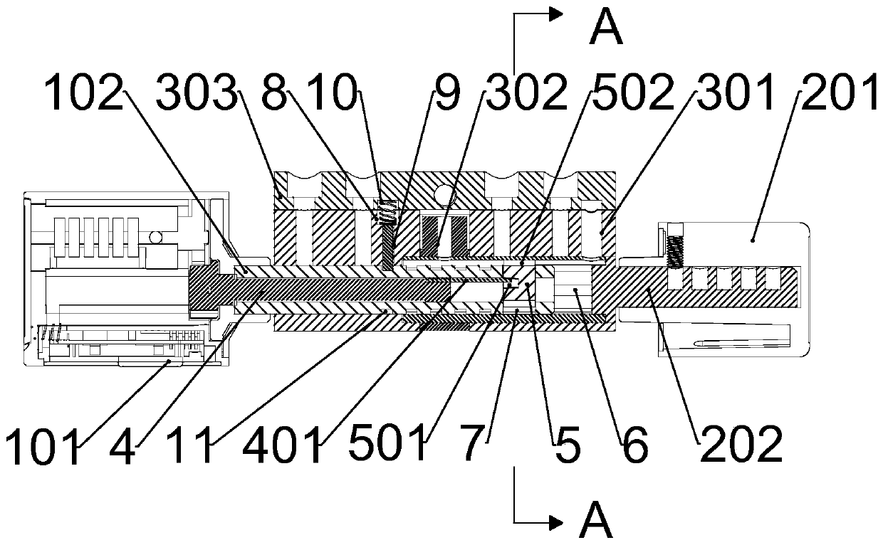
[0026] This embodiment discloses a kind of, such as Figure 1-6As shown, a clutch mechanism of an electronic lock cylinder includes a front handle assembly 1 assembled in the axial direction, a rear handle assembly 2 and a lock cylinder body 3 between them. The front handle assembly 1 includes a front The handle 101, the front main shaft 102 that rotates synchronously with the front handle 101, the rear handle assembly 2 includes the rear handle 201 and the rear main shaft 202 that rotates synchronously with the rear handle 201, the rear main shaft 202 is sleeved on the front main shaft 102, A clutch mechanism is arranged inside the front main shaft 102, and the clutch mechanism includes a lock core shaft 4 and a claw 5 that are forward and reverse relative to the front main shaft 102. The toggling lever 401 is made of steel wire with certain elasticity and ...


PUM


Abstract

The invention discloses a clutch mechanism of an electronic lock cylinder. The clutch mechanism comprises a front handle assembly, a rear handle assembly and a lock cylinder body, wherein the rear handle assembly comprises a front spindle and a rear spindle. The front spindle and the rear spindle each comprise a front handle and a rear handle, the front spindle and the rear spindle are arranged ina synchronous rotation mode, the rear spindle sleeves the front spindle, the front spindle is internally provided with a clutch mechanism body, the clutch mechanism body includes a lock cylinder shaft and a pawl, a poke rod is eccentrically arranged at one end of the lock cylinder shaft, a through hole is provided on the side wall of one end of the front spindle, the claw is slidably disposed inthe through hole, clamping protrusions are symmetrically arranged on the two sides of the pawl, a plurality of racks are symmetrically arranged on the inner wall of the rear spindle, the clamping protrusions on one side of the rear spindle can be engaged with the racks to realize one-way driving of the rear spindle, and the poke rod drives the clamping protrusions on the other side of the claw tobe engaged with the reversing of the racks after the lock cylinder shaft rotates reversely. The clutch mechanism has the effects that locking is convenient and fast, the structure is simple, and the electric quantity is saved.

Description

technical field [0001] The invention relates to the technical field of an electronic lock cylinder, more specifically, it relates to a clutch mechanism of an electronic lock cylinder. Background technique [0002] The cost of the electronic lock cylinder is low and the installation method is similar to the current mechanical lock cylinder, which has attracted widespread attention. However, the internal mechanical structure of the electronic lock cylinder is very compact, and the internal space is difficult to accommodate the structural components required for both mechanical and electronic unlocking. Therefore, existing products are basically single-function electronic lock cylinders, omitting the mechanical unlocking function, and mainly based on electronically driven electronic lock cylinders. [0003] The Chinese patent with the notification number CN201821116556.7 discloses a clutch mechanism for an electronic lock cylinder, which includes a front handle assembly, a rear...

Claims


Application Information

Patent Timeline
IPC IPC(8): E05B47/00E05B15/00
CPCE05B15/00E05B47/0001E05B2047/0026
Inventor 唐志雄
Owner 浙江科利智能科技有限公司
Why Eureka
Try Eureka