Deformable assembly for downhole tool and downhole tool

A technology of downhole tools and deformable parts, which is applied in wellbore/well parts, earthwork drilling, sealing/isolation, etc. It can solve the problems of limited annular space and large sealing mechanism, and achieve the effect of increasing the expansion rate

Pending Publication Date: 2020-06-30
VERTECHS PETROLEUM TECH INNOVATION & EQUIP MFG CO LTD
View PDF0 Cites 2 Cited by
  • Summary
  • Abstract
  • Description
  • Claims
  • Application Information

AI Technical Summary

Problems solved by technology

[0002] Wellbore isolation tools such as bridge plugs and fracturing plugs currently on the market are usually composed of an axially moving anchor assembly, a sealing mechanism, and a mand

Method used


Image

  • Deformable assembly for downhole tool and downhole tool
  • Deformable assembly for downhole tool and downhole tool
  • Deformable assembly for downhole tool and downhole tool

Examples


Embodiment 3

[0065] For the sectional view of embodiment three, see Figure 6 , compared with Embodiment 1, the difference lies in that the inner surface of the deformable part of the deformable assembly main body 1 has a tapered structure. The inner surface has a tapered structure, which is convenient for adapting to the tapered shaft core, and the entire downhole tool is relatively short.

Embodiment 4

[0066] For the cross-sectional view of embodiment four, see Figure 7 , compared with the second embodiment, the difference lies in that the inner surface of the deformable part of the deformable assembly main body 1 has a tapered structure. The inner surface has a tapered structure, which is convenient for adapting to the tapered shaft core, and the entire downhole tool is relatively short.

Embodiment 5

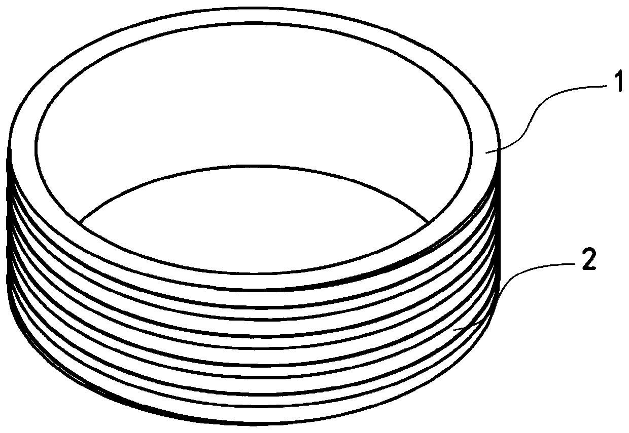
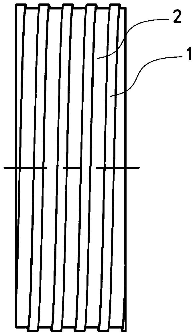
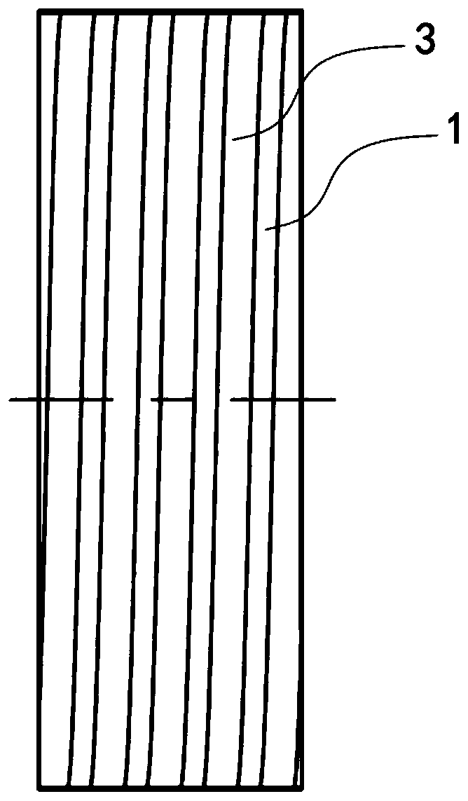
[0067] For the structural diagram of Embodiment 5, see Figure 8 , Figure 9 and Figure 10 , compared with the third embodiment, the difference is that the depth direction of the spiral groove structure 2 runs through the entire deformable component body 1; the spiral groove structure 2 is filled with sealing material 3 .

[0068] Since the depth direction of the spiral groove structure 2 runs through the entire deformable component body 1, the deformable component is in the shape of a spring as a whole. When the sealing material 3 is arranged in the spiral groove structure, the sealing material 3 can be on the outside of the deformable component body 1 and The inner side of the main body of the deformable component forms a sealing structure to ensure the sealing effect.

[0069] For the structure and working state diagram of the first embodiment of the downhole tool, please refer to Figure 11 and Figure 12 . Including the mandrel 5, the deformable assembly is the defo...


PUM


Abstract

The invention relates to the field of petroleum downhole construction, and particularly relates to a deformable assembly for a downhole tool and the downhole tool. The deformable assembly comprises adeformable assembly body, wherein the deformable assembly body is provided with a deformable piece outer surface and a deformable piece inner surface; the deformable piece inner surface is used for being matched with a mandrel deformable surface for installation; at least one circle of complete spiral groove structure is arranged in the circumferential direction of the deformable piece outer surface of the deformable assembly body; the depth direction of the spiral groove structure is that the spiral groove structure extends from the deformable piece outer surface to the deformable piece innersurface; and a sealing material is arranged in the spiral groove structure. At least one circle of complete spiral groove structure is arranged in the circumferential direction of the deformable assembly body, so that the surface area of the deformable assembly body is increased, and the expansion rate of the deformable assembly body is increased; and due to the fact that the sealing material isarranged in the spiral groove structure, the sealing material achieves sealing with the inner wall of a shaft.

Description

technical field [0001] The invention relates to the field of petroleum downhole construction, in particular to a deformable component for downhole tools and the downhole tool. Background technique [0002] Wellbore isolation tools such as bridge plugs and fracturing plugs currently on the market are usually composed of an axially moving anchor assembly, a sealing mechanism, and a mandrel. When sealing downhole, the annular space that can achieve effective sealing after expansion is limited. , Usually the expansion rate is 3%-20%, so the sealing mechanism will be larger. Contents of the invention [0003] The technical problem to be solved by the present invention is to provide a deformable component for downhole tools and the downhole tool, and improve the expansion rate of the deformable component. [0004] The technical solution of the present invention to solve the above-mentioned technical problems is as follows: a deformable component for downhole tools, including a ...

Claims


Application Information

Patent Timeline
IPC IPC(8): E21B33/12E21B33/128E21B33/134
CPCE21B33/12E21B33/128E21B33/134
Inventor 曾琦军江传龙
Owner VERTECHS PETROLEUM TECH INNOVATION & EQUIP MFG CO LTD
Why Eureka
Try Eureka