LED light source assembly and high-power lamp using LED light source assembly

A technology of LED light source and LED light strip, which is applied in the direction of semiconductor devices, light sources, electric light sources, etc. of light-emitting elements, which can solve the problems of high price, large volume and heavy weight of LED lights, and solve the problem of heat dissipation and avoid volume increase , The effect of improving assembly efficiency

Pending Publication Date: 2020-06-30
ZHEJIANG SUNSHINE MEIJIA LIGHTING CO LTD +1
View PDF0 Cites 1 Cited by
  • Summary
  • Abstract
  • Description
  • Claims
  • Application Information

AI Technical Summary

Problems solved by technology

In order to solve this technical problem, it is necessary to use a radiator to dissipate heat. Usually, LEDs are installed on the surface of the radiator to dissipate heat. However, the greater the power of the LED, the larger the volume of the radiator is required. In this way, not only the volume of the LED lamp will be increased Larger, heavier, and more expensive

Method used


Image

  • LED light source assembly and high-power lamp using LED light source assembly
  • LED light source assembly and high-power lamp using LED light source assembly
  • LED light source assembly and high-power lamp using LED light source assembly

Examples


Embodiment 1

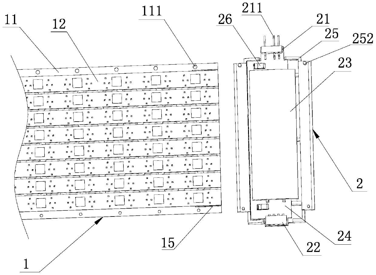
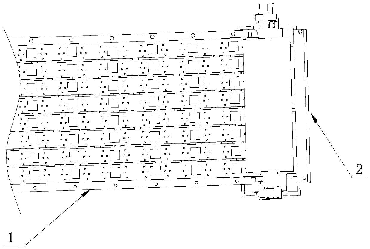
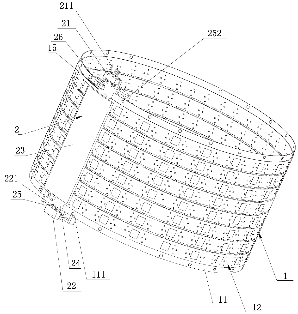
[0038] A kind of LED light source assembly proposed in this embodiment, such as Figure 1 to Figure 8 As shown, it includes an LED light source board 1 and an electrical connector 2. The LED light source board 1 has a bar-shaped structure. The LED light source board 1 has two electrodes 11 arranged along the length direction and parallel to each other. One end of the electrical connector 2 has a plug The needle assembly 21 and the other end has a socket assembly 22, so that one end of the length direction of the LED light source board 1 is connected to one side of the electrical connector 2, and the other end of the length direction of the LED light source board 1 is connected to the electrical connector 2 after the LED light source board 1 is curled. The other side of the connector 2 is connected, and the pin assembly 21 is electrically connected to one electrode 11 close to it, and the socket assembly 22 is electrically connected to the other electrode 11 close to it, forming...

Embodiment 2

[0046] This embodiment proposes a high-power lamp using the LED light source assembly of Embodiment 1, such as Figure 9 to Figure 18 As shown, it includes a lamp cap 3, a lamp body 4, a driving power supply 5 arranged in the lamp body 4, three LED light source assemblies G, a top layer ring 7, a top layer light source board 8, an annular mask 9, the lamp cap 3 and the lamp The narrow mouth of the body 4 is connected, the top layer light source board 8 is installed on the top of the top layer ring 7, the annular mask 9 is covered outside the top layer light source board 8 and connected with the top of the top layer ring 7, and passes between two adjacent LED light source assemblies G The connecting ring 6 is connected, the top of the wide mouth of the lamp body 4 is connected to the bottom of the bottom LED light source assembly G, the top layer ring 7 is connected to the top of the top LED light source assembly G, and the bottom LED light source The socket assembly 22 in the ...


PUM


Abstract

The invention discloses an LED light source assembly and a high-power lamp using the LED light source assembly. The LED light source assembly comprises an LED light source plate and an electric connector. The LED light source plate is provided with two electrodes which are arranged in the length direction and are parallel to each other. One end of the electric connector is provided with a pin assembly and the other end is provided with a socket assembly. One end of the LED light source plate in the length direction is connected with one side of the electric connector; after the LED light source plate is curled, the other end of the LED light source plate in the length direction is connected with the other side of the electric connector, the pin assembly is electrically connected with one electrode close to the pin assembly, the socket assembly is electrically connected with the other electrode close to the socket assembly, and the LED light source assembly which is integrally of a cylindrical structure is formed; the LED light source assembly has the advantages that a radiator is not needed, a good heat dissipation effect is achieved, the weight is light and the price is low.

Description

technical field [0001] The invention relates to an LED product, in particular to an LED light source assembly and a high-power lamp using the LED light source assembly. Background technique [0002] LED has gradually replaced traditional incandescent lamps and energy-saving lamps due to its advantages of energy saving, high efficiency, and environmental protection, and is widely used in ordinary households. [0003] Since the LED is a point light source with a small area, only 30-50% of the input electric energy is output in the form of light, and the remaining 50-70% of the electric energy is released in the form of heat, so the heat generated by the LED is large and concentrated. At the same time, heat has a greater impact on LED luminescence. In order to solve this technical problem, it is necessary to use a radiator to dissipate heat. Usually, LEDs are installed on the surface of the radiator to dissipate heat. However, the greater the power of the LED, the larger the v...

Claims


Application Information

Patent Timeline
Patent Type & Authority Applications(China)
IPC IPC(8): F21S2/00F21V23/06F21V19/00F21Y115/10
CPCF21S2/005F21V23/06F21V19/003F21Y2115/10
Inventor 付超李阳马正红章冰霜章渭君
Owner ZHEJIANG SUNSHINE MEIJIA LIGHTING CO LTD
Why Eureka
Try Eureka