Drying oven
A drying box and box technology, which is used in drying chambers/containers, drying solid materials, local stirring dryers, etc., can solve the problems of wasting energy, time-consuming, and unstable placement of round utensils, and shortening the time. , the effect of convenient registration
- Summary
- Abstract
- Description
- Claims
- Application Information
AI Technical Summary
Problems solved by technology
Method used
Image


Examples
Embodiment 1
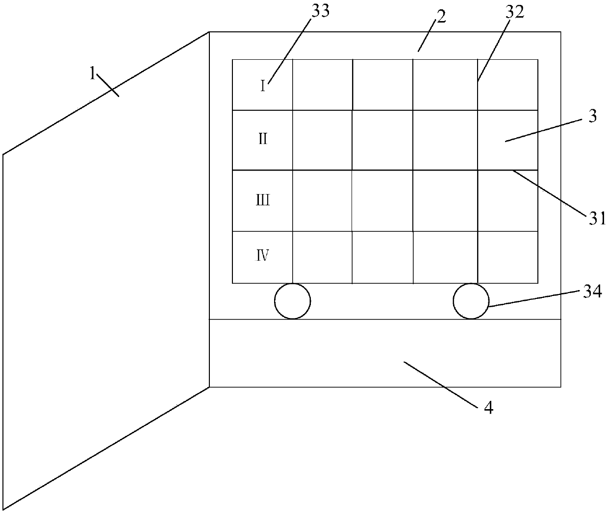
[0025] See also figure 1 and figure 2 , figure 1 A schematic diagram of the structure of a drying oven when the door is opened for the embodiment of the present invention; figure 2 It is a schematic diagram of the structure of a drying box when the door of the drying oven is closed according to the embodiment of the present invention. A drying box, comprising: a door 1, a box body 2, a shelf 3 and a temperature and humidity control box 4; the shelf 3 is arranged inside the box body 2, and the shelf 3 includes a shelf 31, A plate 32 and a door 33, the baffle 32 is arranged in parallel in the box body 2, the baffle 32 is located between the shelves 31 and is perpendicular to the shelf 31, the baffle 33 and The baffle 32 is vertical and perpendicular to the shelf 31 , and four corners of the bottom of the shelf 2 are provided with rollers 34 .
[0026] Further, the roller 34 is a universal wheel.
[0027] Further, several grooves are provided on the shelf 31 .
[0028] Fu...
Embodiment 2
[0037] The embodiment of the present invention introduces the structure of the drying box in detail on the basis of the above embodiments.
[0038] see again figure 1 and figure 2 , a drying box, comprising: a box door 1, a box body 2, a shelf 3 and a temperature and humidity control box 4; the shelf 3 is arranged inside the box body 2.
[0039] Generally, the common drying box only has a box body, a support plate, a partition and a temperature and humidity control box, which realizes a simple drying function. Shelf 3, said rack 3 comprises a shelf 31, a baffle 32 and a door 33, said baffle 32 is used to divide said box body 2 into several small grids, and said door 33 is used to carry out small grids Isolation to prevent dust or other impurities from falling into the liquid or solid to be dried placed in the small grid, causing pollution. The baffle 32 is arranged in parallel in the box body 2, the baffle 32 is located between the shelves 31 and is perpendicular to the sh...
PUM
| Property | Measurement | Unit |
|---|---|---|
| Diameter | aaaaa | aaaaa |
Abstract
Description
Claims
Application Information
 - R&D
- Intellectual Property
- Life Sciences
- Materials
- Tech Scout
- Unparalleled Data Quality
- Higher Quality Content
- 60% Fewer Hallucinations
Browse by: Latest US Patents, China's latest patents, Technical Efficacy Thesaurus, Application Domain, Technology Topic, Popular Technical Reports.
© 2025 PatSnap. All rights reserved.Legal|Privacy policy|Modern Slavery Act Transparency Statement|Sitemap|About US| Contact US: help@patsnap.com