
Environment detection sampling device

A sampling device and environmental detection technology, which is applied in the direction of sampling devices, can solve the problems of laborious sampling efficiency and low efficiency, and achieve the effect of improving the overall efficiency

Pending Publication Date: 2020-06-30
LULIANG UNIV
View PDF6 Cites 5 Cited by
  • Summary
  • Abstract
  • Description
  • Claims
  • Application Information

AI Technical Summary

Problems solved by technology

[0002] In the traditional environmental sampling process, soil sampling requires the use of a sampling rod. A single operation needs to insert the sampling rod into the soil and then pull it out before collecting. The sampling efficiency is laborious and inefficient

Method used


Image

  • Environment detection sampling device
  • Environment detection sampling device
  • Environment detection sampling device

Examples


Embodiment 1

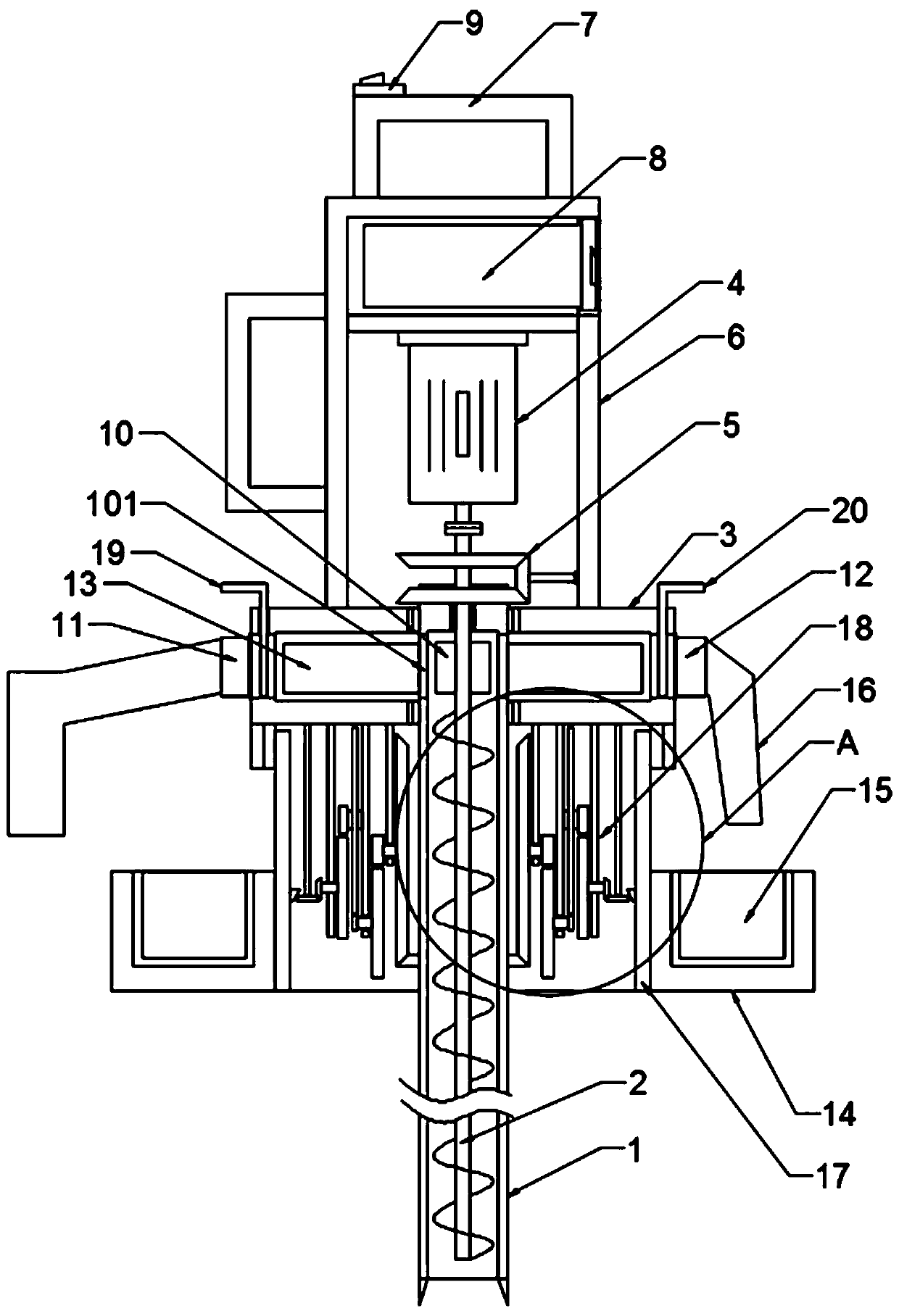
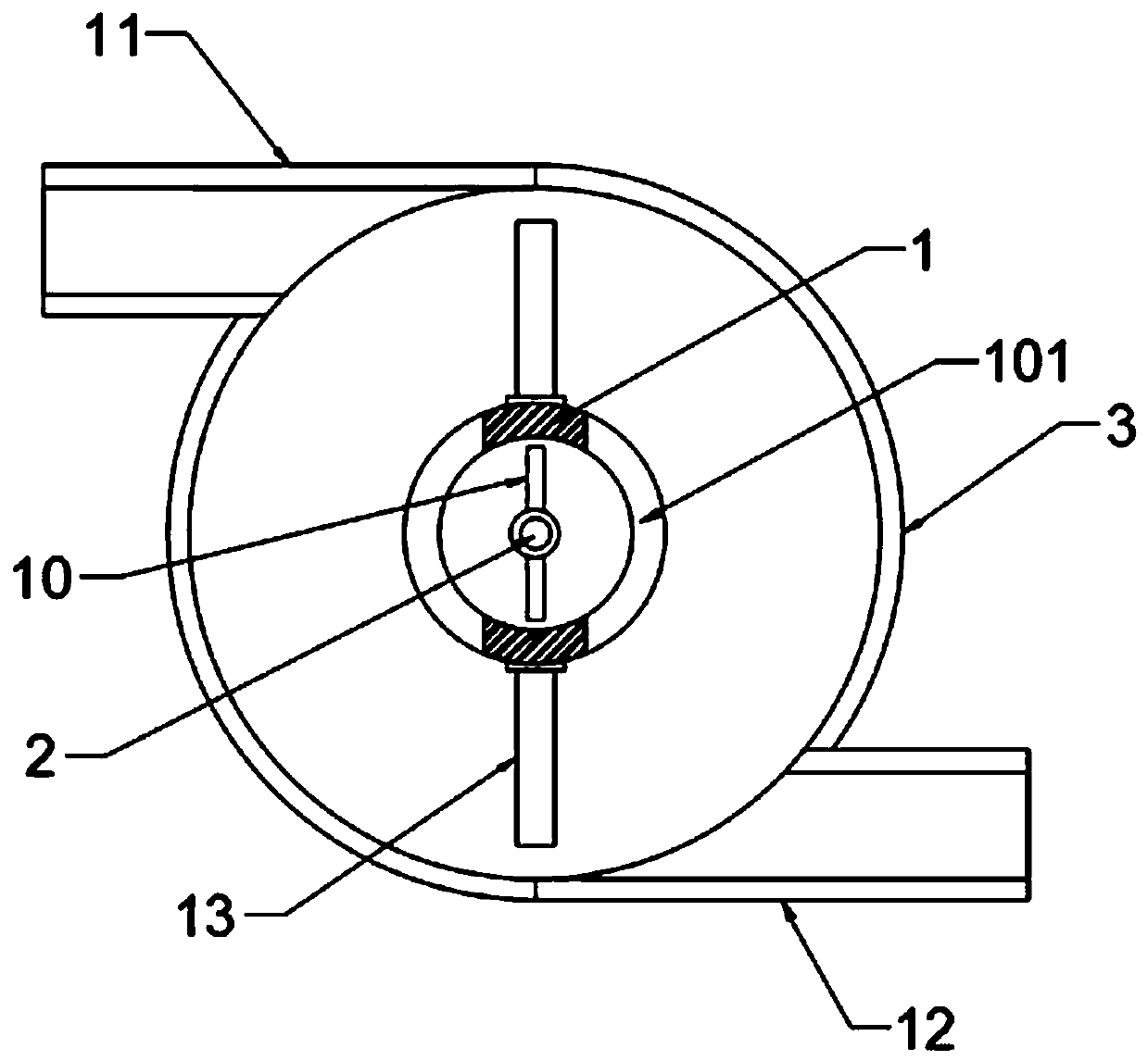
[0022] see Figure 1-5 , in an embodiment of the present invention, an environmental detection sampling device includes a device body; the device body includes a soil collection mechanism; the soil collection mechanism includes a drill barrel 1, and a screw conveyor roller is nested in the drill barrel 1 2. Dispersion cylinder 3 runs through the upper part of drill cylinder 1 and extends to the top of dispersion cylinder 3. Drill cylinder 1 is rotationally connected with dispersion cylinder 3 through a bearing sleeve, and the screw feed roller 2 extends to the top of drill cylinder 1; the screw feed roller 2. A drive motor 4 is connected through a coupling, and the screw feed roller 2 is connected to the drill barrel 1 for transmission through a transmission gear set 5; specifically, the drive motor 4 drives the screw feed roller 2 to rotate, and the screw feed roller 2 drives the drill barrel 1 Rotate, the rotation direction of the drill tube 1 is opposite to the rotation dir...

Embodiment 2

[0027] An environmental detection and sampling device, comprising a device body; the device body includes a soil collection mechanism; the soil collection mechanism includes a drill tube 1, a screw feed roller 2 is embedded in the drill tube 1, and the upper part of the drill tube 1 runs through the There is a dispersion cylinder 3 and extends to the top of the dispersion cylinder 3, the drill cylinder 1 is rotationally connected with the dispersion cylinder 3 through a bearing sleeve, and the screw feed roller 2 extends to the top of the drill cylinder 1; the screw feed roller 2 is connected with a The drive motor 4 and the screw feed roller 2 are connected and driven by the transmission gear set 5 with the drill barrel 1; specifically, the drive motor 4 drives the screw feed roller 2 to rotate, the screw feed roller 2 drives the drill barrel 1 to rotate, and the drill barrel 1 rotates in the direction Contrary to the rotation direction of the screw feed roller 2, when the dri...

Embodiment 3

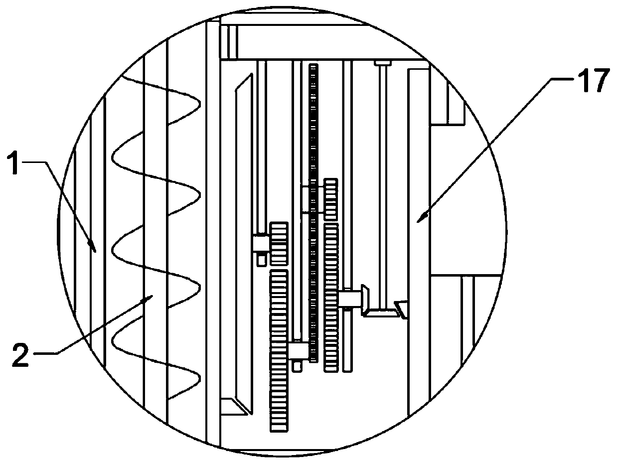
[0033] The difference between this embodiment and Embodiment 2 is that in order to realize the automatic sorting and loading of samples, the inner side of the drum 17 is connected to the drill tube 1 through a reduction gear set 18 for transmission, and the reduction gear set 18 transmits the power of the drill tube 1 to the rotary drum 1. Drum 17, rotating drum 17 drives the annular seat 14 to rotate slowly; specifically, the reduction gear set 18 includes multiple sets of small gears, large gears, and bevel gear rings, which are common transmission gear sets, and will not be described in detail in this application.


PUM


Abstract

The invention discloses an environment detection sampling device. The environment detection sampling device comprises a device body; and the device body comprises a soil sampling and collecting mechanism, the soil sampling and collecting mechanism comprises a drilling barrel, a spiral conveying roller is nested in the drilling barrel, a dispersing barrel penetrates through the upper part of the drilling barrel, the spiral conveying roller is connected with a driving motor through a shaft coupling, and the spiral conveying roller is in transmission connection with the drilling barrel through atransmission gear set. Through the arrangement of the drilling barrel with a discharging opening formed in the upper portion, an inner material stirring plate connected with the spiral material conveying roller, an outer scraping plate fixedly connected with the drilling barrel, the dispersing barrel, a discharging pipe and a collecting pipe, soil of different depths is lifted, soil of non-targetdepths is discharged, soil of target depths is collected, and accurate sampling of soil of the designated depth is achieved; and through the arrangement of a material guide pipe and a bearing seat which is linked with the drilling barrel and rotates, soil of different depths is collected and stored in a classified mode, classified collection of samples is achieved, and the overall efficiency of soil sampling is improved.

Description

technical field [0001] The invention relates to the field of environmental sampling equipment, in particular to an environmental detection sampling device. Background technique [0002] In the traditional environmental sampling process, soil sampling requires the use of a sampling rod. A single operation needs to insert the sampling rod into the soil, and then pull it out before collecting. The sampling efficiency is laborious and inefficient. Contents of the invention [0003] The object of the present invention is to provide an environmental detection sampling device to solve the problems raised in the above-mentioned background technology. [0004] To achieve the above object, the present invention provides the following technical solutions: [0005] An environmental detection sampling device, including a device body; the device body includes a soil collection mechanism, the soil collection mechanism includes a drill tube, a screw feed roller is nested in the drill tub...

Claims


Application Information

Patent Timeline
Patent Type & Authority Applications(China)
IPC IPC(8): G01N1/08
CPCG01N1/08
Inventor 李杰锋
Owner LULIANG UNIV
Learn More