Eureka AIR delivers breakthrough ideas for toughest innovation challenges, trusted by R&D personnel around the world.

Liquid crystal display panel, manufacturing method thereof, and liquid crystal display device

A technology for a liquid crystal display panel and a manufacturing method, applied in nonlinear optics, instruments, optics, etc., can solve problems such as process condition limitations, product yield reduction, connection defects, etc., to avoid length differences, improve product yield, Realize the effect of narrow border

Active Publication Date: 2020-06-30
BOE TECH GRP CO LTD +1
View PDF8 Cites 11 Cited by
  • Summary
  • Abstract
  • Description
  • Claims
  • Application Information

AI Technical Summary

Problems solved by technology

[0003]At present, TFT-LCD is developing towards the direction of narrow frame, but limited by actual process conditions, the distance between COF (Chip On Film, chip-on-film) and array substrate There are certain defects in the connection, which leads to a decrease in product yield

Method used


Image

  • Liquid crystal display panel, manufacturing method thereof, and liquid crystal display device
  • Liquid crystal display panel, manufacturing method thereof, and liquid crystal display device
  • Liquid crystal display panel, manufacturing method thereof, and liquid crystal display device

Examples


Embodiment Construction

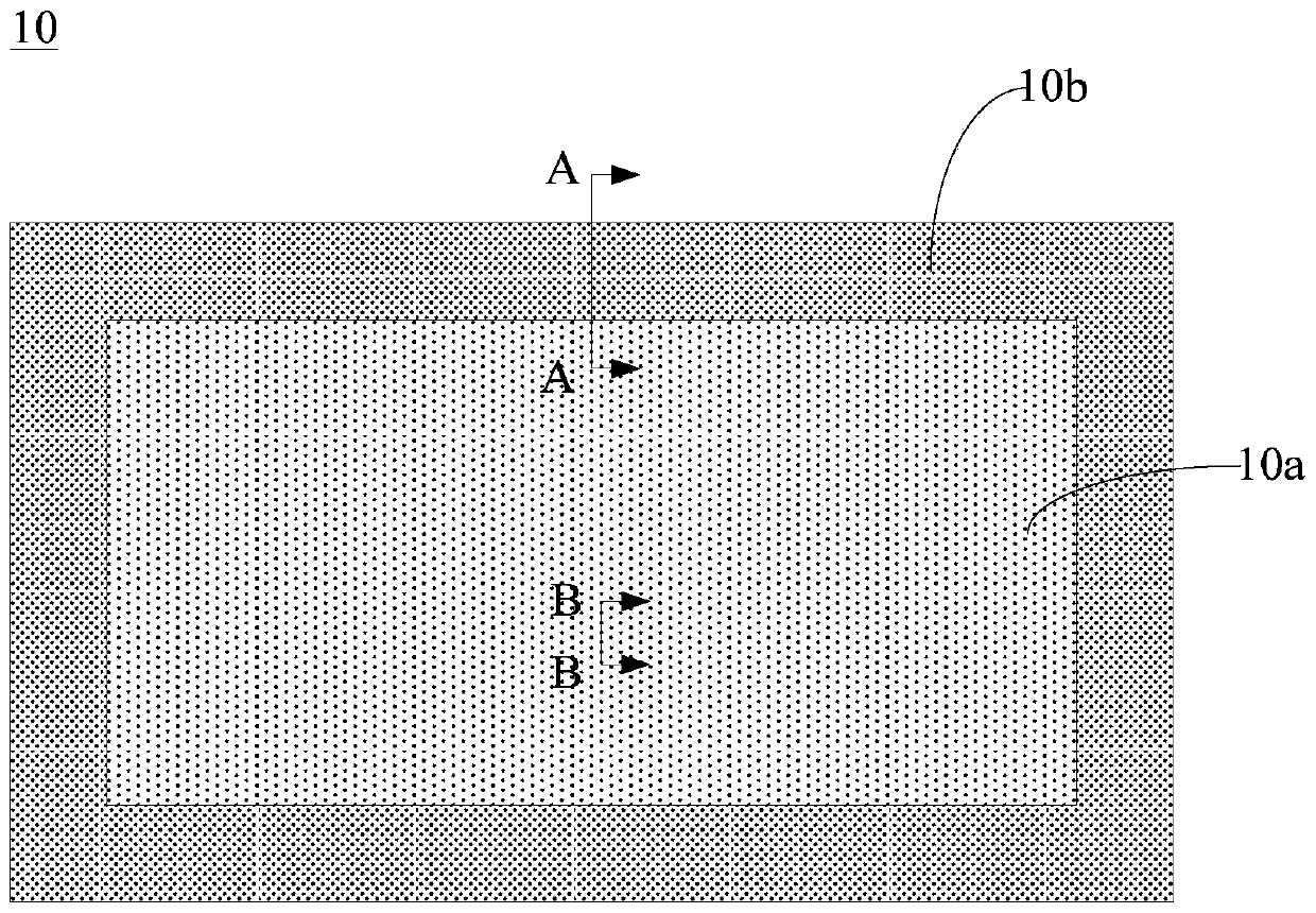
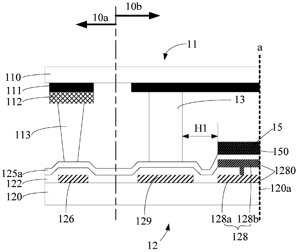
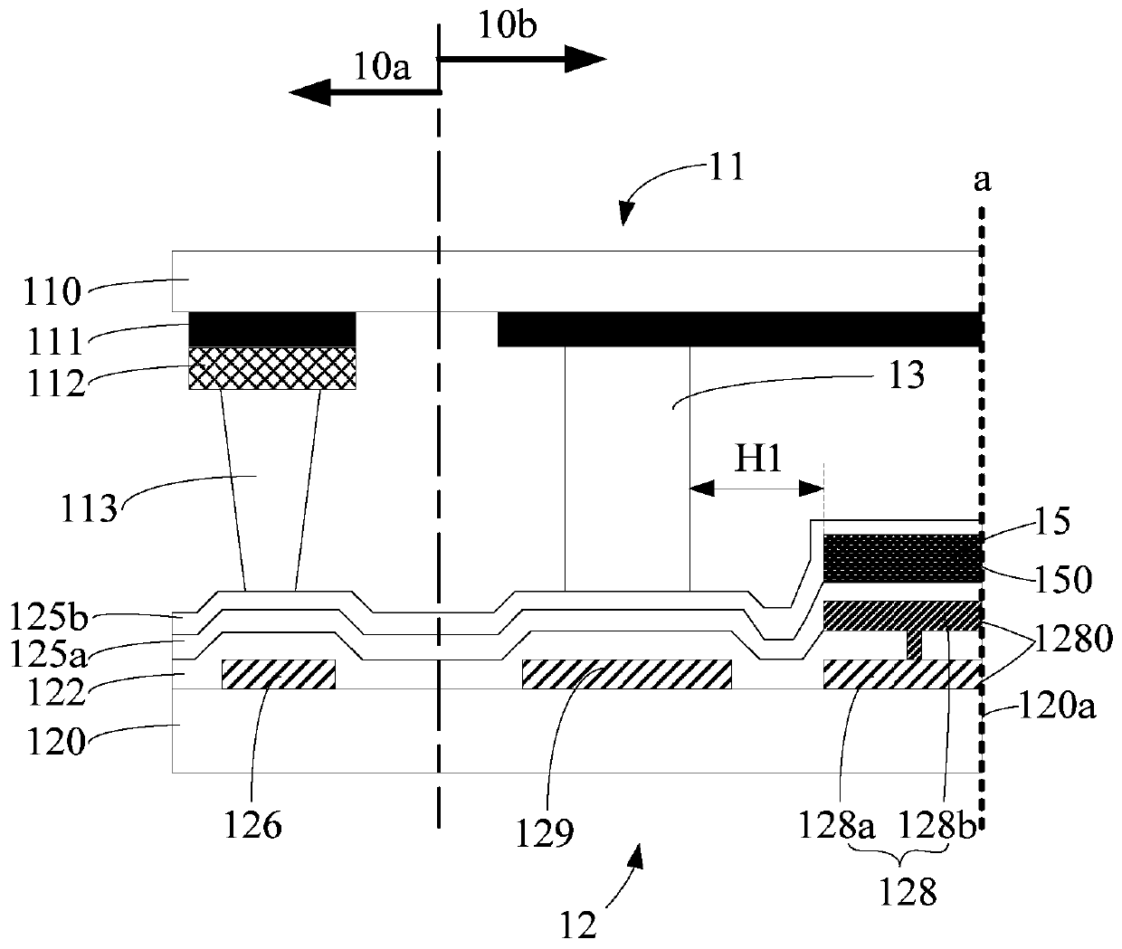
[0060] The technical solution of the present disclosure will be further described in detail through the following embodiments and in conjunction with the accompanying drawings. In the specification, the same or similar reference numerals designate the same or similar components. The following description of the embodiments of the present disclosure with reference to the accompanying drawings is intended to explain the general inventive concept of the present disclosure, and should not be construed as a limitation of the present disclosure.

[0061] In addition, in the following detailed description, for purposes of explanation, numerous specific details are set forth in order to provide a comprehensive understanding of the embodiments of the present disclosure. It may be evident, however, that one or more embodiments may be practiced without these specific details.

[0062] It should be noted that "on", "formed on" and "arranged on" mentioned in this article may mean that one...


PUM

PropertyMeasurementUnit
Thicknessaaaaaaaaaa

Abstract

The invention relates to the technical field of display, and concretely relates to a liquid crystal display panel, a manufacturing method thereof, and a liquid crystal display device. The liquid crystal display panel is provided with a display area and a non-display area surrounding the display area, the liquid crystal display panel comprises a color film substrate, an array substrate and a framesealing glue, the color film substrate and the array substrate are arranged in a box-to-box mode, the frame sealing glue is located between the color film substrate and the array substrate, and the frame sealing glue is located in the non-display area. The array substrate comprises: a first base with a substrate section; an extraction electrode, wherein the extraction electrode is formed on the first base, is located in the non-display area and is located on the side, away from the display area, of the frame sealing glue, and the extraction electrode is provided with a binding section away from the display area; and a protective film layer formed on the side, away from the first base, of the extraction electrode, wherein the protective film layer has a film layer section away from the display area, and the binding section, the substrate section and the film layer section are located in the same plane. According to the liquid crystal display panel, a narrow frame is achieved, and meanwhile the product yield can be increased.

Description

technical field [0001] The present disclosure relates to the field of display technology, in particular, to a liquid crystal display panel, a method for manufacturing the liquid crystal display panel, and a liquid crystal display device. Background technique [0002] With the continuous development of display technology, thin film transistor liquid crystal display (Thin Film Transistor Liquid Crystal Display, TFT-LCD for short) has occupied a dominant position in the field of flat panel display. [0003] At present, TFT-LCD is developing in the direction of narrow borders, but limited by actual process conditions, there are certain defects in the connection between COF (Chip On Film, chip-on-film) and the array substrate, resulting in a decrease in product yield. [0004] It should be noted that the information disclosed in the above background section is only for enhancing the understanding of the background of the present disclosure, and therefore may include information t...

Claims


Application Information

Patent Timeline
IPC IPC(8): G02F1/1333G02F1/1343G02F1/1339G02F1/1345
CPCG02F1/1333G02F1/1343G02F1/1339G02F1/13452G02F1/13394G02F1/13396
Inventor 王孟杰刘晓那
Owner BOE TECH GRP CO LTD
Why Eureka
Eureka Blog
Learn More