DC circuit breaker

A technology of DC circuit breaker and current sensor, applied in circuit devices, emergency protection circuit devices, emergency protection devices with automatic disconnection, etc., can solve the problems of slow reclosing speed, etc.

Active Publication Date: 2020-06-30
PINGGAO GRP +2
View PDF14 Cites 2 Cited by
  • Summary
  • Abstract
  • Description
  • Claims
  • Application Information

AI Technical Summary

Problems solved by technology

[0006] The purpose of the present invention is to provide a DC circuit breaker, which is used to solve the problem of slow reclosing speed caused by the voltage on the transfer capacitor being reduced to zero or retaining a certain forward voltage after the DC circuit breaker is broken in the prior art. question

Method used


Image

  • DC circuit breaker
  • DC circuit breaker
  • DC circuit breaker

Examples


Embodiment 1

[0041] This embodiment provides a DC circuit breaker, which reversely charges the transfer capacitor after the DC circuit breaker is broken, so that the DC circuit breaker can be quickly reclosed.

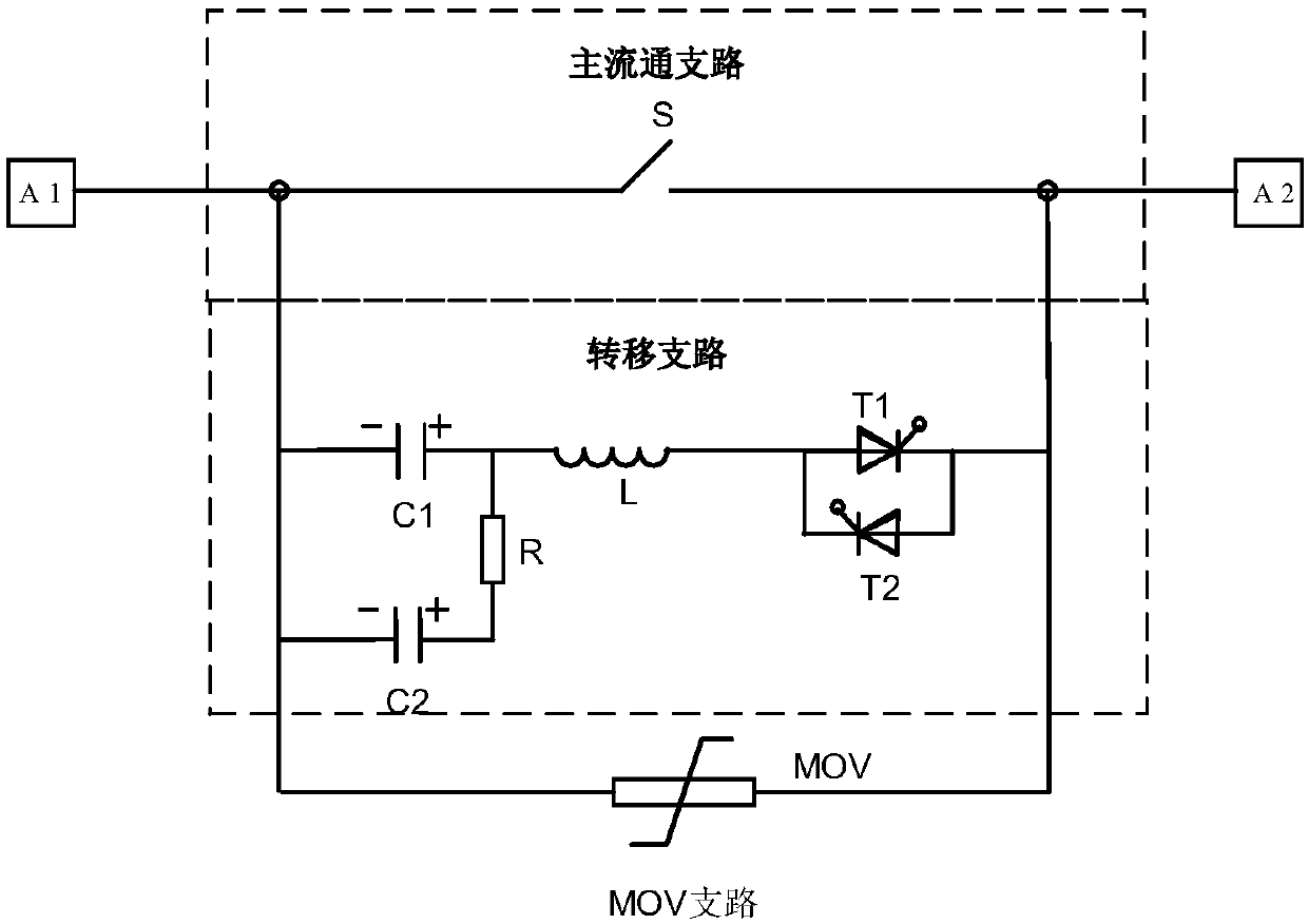
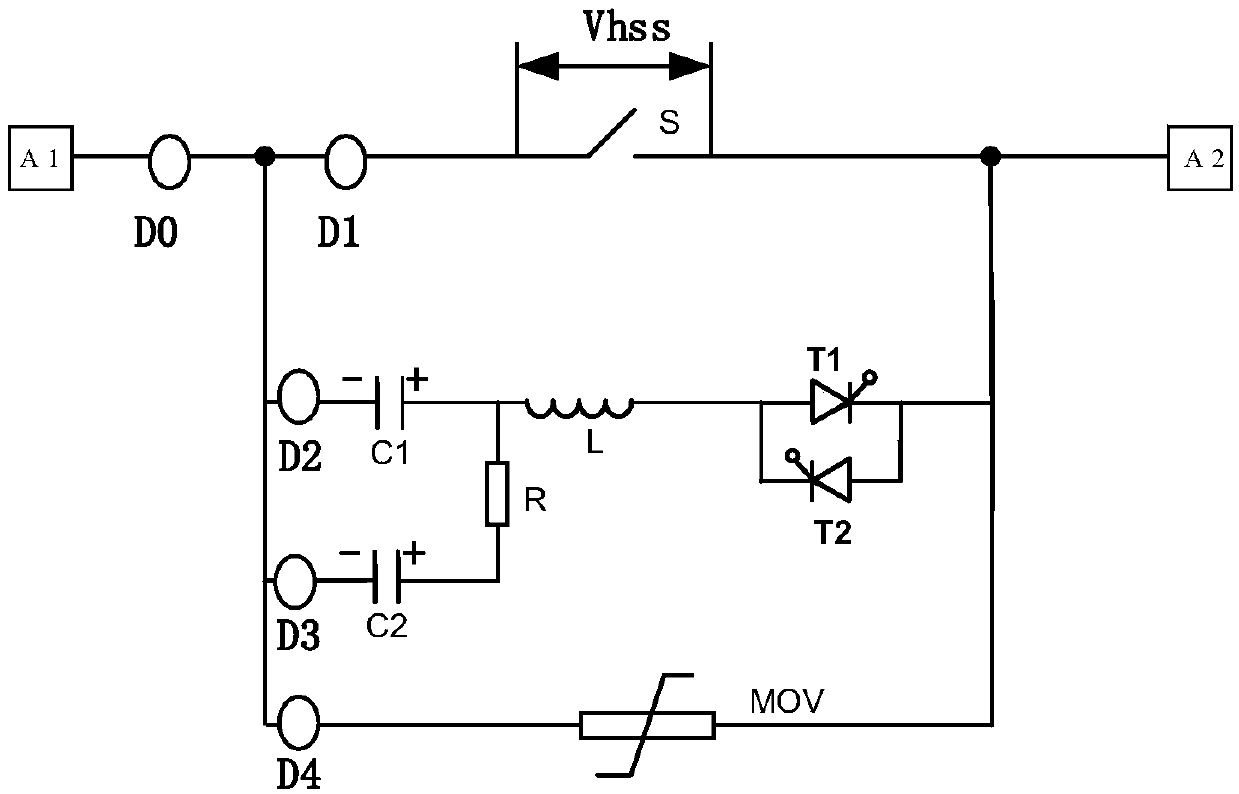
[0042] The structure principle of the DC circuit breaker provided in this embodiment is as follows: figure 1 As shown, it includes the main circulation branch, the transfer branch and the MOV branch arranged in parallel, and the terminals A1 and A2 are the two ends of the parallel connection of the main circulation branch, transfer branch and MOV branch.

[0043] A mechanical switch S is arranged in the main flow branch, and the mechanical switch S is a high-speed mechanical switch; an arrester MOV for energy consumption is arranged in the MOV branch.

[0044] The transfer branch includes a transfer capacitor C1, a transfer inductance L, and a transfer switch. In this embodiment, the transfer capacitor C1, the transfer inductance L, and the transfer switch are arranged in series in...

Embodiment 2

[0068] This embodiment provides a DC circuit breaker. Compared with the DC circuit breaker provided in Embodiment 1 above, the difference between this DC circuit breaker is that no transfer inductance is set in the transfer branch, such as Image 6 As shown; the working principle of the DC circuit breaker provided in this embodiment is the same as that provided in Embodiment 1 above.


PUM


Abstract

The invention provides a DC circuit breaker, which comprises a main circulation branch, a transfer branch and an MOV branch. The transfer branch is provided with a transfer capacitor and a transfer switch in series; the two ends of the transfer capacitor are provided with pre-charging branches in parallel. A charging capacitor and a current-limiting resistor are arranged on each pre-charging branch in series; the current-limiting resistor is used for enabling the current on the main circulation branch not to be transferred to the pre-charging branch in the breaking process of the DC circuit breaker, and the charging capacitor charges the transfer capacitor through the current-limiting resistor after the breaking process is finished, thereby enabling the transfer capacitor to be charged with a certain reverse voltage. According to the provided technical scheme, the pre-charging branches are arranged on the transfer capacitor in parallel; after the DC circuit breaker is disconnected, thepre-charging branches charge the transfer capacitor and thus the transfer capacitor is charged with a certain reverse voltage, thereby reducing the reverse charging time of the transfer capacitor before the DC circuit breaker is reclosed, and solving a problem that the reclosing speed of the DC circuit breaker is slower.

Description

technical field [0001] The invention belongs to the technical field of direct current circuit breaker control, and in particular relates to a direct current circuit breaker. Background technique [0002] At present, the DC power supply technology has been widely used in our country, and the DC circuit breaker is a very important device in the DC power supply system. According to the working principle of DC circuit breakers, it can be divided into mechanical circuit breakers, all solid state circuit breakers and hybrid circuit breakers. Among them, hybrid circuit breakers have the advantages of less on-state loss, short breaking time, and no need for special cooling. , are widely used in DC power supply systems. [0003] The Chinese utility model patent document with the authorized notification number CN206180562U discloses a DC circuit breaker, in which a transfer switch, a transfer inductance and a transfer capacitor are arranged in series on the transfer branch. The tran...

Claims


Application Information

Patent Timeline
Patent Type & Authority Applications(China)
IPC IPC(8): H02H3/06H02H3/087
CPCH02H3/066H02H3/087
Inventor 庞素敏肖宇魏源韩桂全韩国辉刘文魁王铭飞李永林张亚辉张智辉吴益飞吴翊
Owner PINGGAO GRP
Why Eureka
Try Eureka