Ankle arthroplasty systems and methods
A technology for ankle joints, articular surfaces, applied in the field of surgical operating systems
Pending Publication Date: 2020-06-30
LIMA CORPORATE SPA
9 Cites 0 Cited by
AI-Extracted Technical Summary
Problems solved by technology
[0004] The various systems and methods of the present disclosure have been developed in response to the current state of the art, and parti...
Method used
In some embodiments, the talus prosthesis 102 and the tibial prosthesis 104 can be inserted in a generally backward direction such that the keel 212 of the talus prosthesis 102 slides backward into the slot 1200 of the surface 620 of the talus 420 , the keels 312 of the tibial prosthesis 104 are slid posteriorly into corresponding slots in the prepared tibial surface 1320 . Notably, some occasional cranial/caudal motion and/or rotation of the talar prosthesis 102 and/or tibial prosthesis 104 may be employed to fully seat the talar prosthesis 102 and tibial prosthesis 104 on their respective prepared surfaces middle. However, it is advantageous to minimize the required dispersion forces in the joint space. Thus, the insertion vectors for the talar prosthesis 102 and the tibial prosthesis 104 may advantageously be primarily posterior.
[0098] In some alternative embodiments (not shown), set nails may be used in addition to or instead of keel 212. Such staples can be of any size or shape known in the art. In some embodiments, the fixation pin may be permanently affixed to the remainder of the talar engagement surface 112 . In other embodiments, the fixation pegs may be modular and may, for example, be attached to receiving features in the bone engaging surface, such as mounting holes. In other embodiments, the fixation pins can be deployed in situ and can be moved from a retracted position to a deployed position to facilitate placement of the talar prosthesis and/or reduce the amount of ankle distraction required for implantation.
[0125] The moving member 502 may also have a tool holder attachment interface, or more specifically, a talar bone drill holder interface that may be attached to a talar bone drill holder in the form of a drill The form holds the cutting tool. The talar drill holder can have a base attachable to the talar drill holder interface. Accordingly, the talar drill holder interface may also be referred to as a base attachment interface. The base attachment interface may be designed to fix the base relative to the moving member 502 such that when the moving member 502 moves relative to the fixed member 500 the moving member 502 carries the base. As will be described later, the base attachment interface can also be used to attach an alignment block to the translation member 502 to facilitate positioning of the tibial base relative to the tibia.
[0177] The tibial base 1300 may also have a tool holder attachment interface, or more specifically, a tibial drill holder interface attachable to a tibial drill holder that holds a drill form of cutting tool. The tibial drill holder can have a base connectable to the talar drill holder interface. Accordingly, the tibial drill holder interface may also be referred to as a base attachment interface. The base attachment interface may be designed to secure the base relative to the tibial base 1300 . Unlike the talar base 410, the tibial base 1300 may have no fixation members and no moving members; and the tibial base 1300 may have no fixation members. Instead, the entire tibial base can serve as a fixed base for the tibial drill holder. As depicted in FIG. 13C , the base attachment interface can also be used to attach the tibial base 1300 to the alignment block 1310 to facilitate ...
Abstract
An ankle arthroplasty system (100) may have a talar prosthesis (102) and a tibial prosthesis (104), each of which has an articular surface (110, 120) and a bone engagement surface (112, 122). Each bone engagement surface may have an anterior-posterior curvature and a medial-lateral curvature with a convex shape. A burr (610, 800, 830, 860) with a rotatable cutting element (720, 820, 850, 880) maybe used to form a prepared surface on the talus or the tibia to receive the corresponding prosthesis. A cutting guide may be used to guide motion of the burr; the cutting guide may include a base andan arm movably coupled to the base. One of the base and the arm may have a guide surface, and the other may have a follower that slides along the guide surface to constrain motion of the burr such that the prepared surface has at least one concave curvature and one convex curvature.
Application Domain
Wrist jointsAnkle joints +2
Technology Topic
Sacroiliac jointBiomedical engineering +14
Image
Examples
- Experimental program(1)
Example Embodiment
[0164] The result can be as Figure 6B and 10B Formation of preparation surface 620 is shown. combine Figure 11A and 11B Fabrication surface 620 will be further shown and described.
[0165] Figure 11A and 11B A side elevational view, a cross-sectional view, and an enlarged cephalic frontal view, respectively, of the talus 420 with the talus base 410, talus burr holder 600, and burr 610 as shown in Figs. Figure 10A and 10B positioning shown. In addition to the slot for the keel 212 of the talar prosthesis 102, the shape of the preparation surface 620 is shown in more detail.
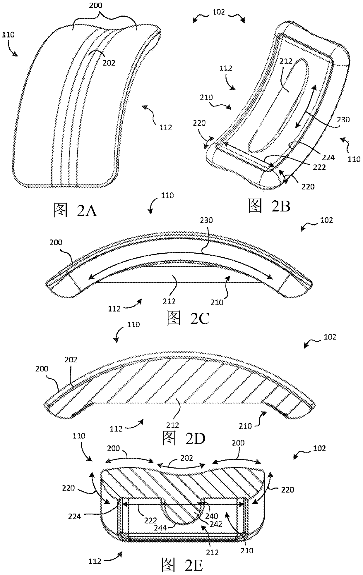
[0166] like Figure 11A As shown, the fabrication surface 620 may have a side cross-sectional shape in planes located in the anterior-posterior direction 130 and the cranio-caudal direction 134, the planes being the same as those shown in Figure 2C The side views of the talar prosthesis 102 shown are closely matched. The preparation surface 620 may have a convex anteroposterior curvature 1100 having a radius substantially the same as the anteroposterior curvature 230 of the talar engaging surface 112 of the talar prosthesis 102. Anterior and posterior to the convex anteroposterior curve 1100, the preparation surface 620 may have two convex anterior and posterior curvatures 1110, the radius of which may be the same as the radius of the portion of the talus bone engaging surface 112 anterior and posterior to the anterior and posterior curvatures 230.
[0167] like Figure 11B As shown, the preparation surface 620 may have a cross-sectional shape in a plane lying in the medial-lateral direction 132 and the cranio-caudal direction 134 that closely matches the cross-sectional shape of the talar bone engaging surface 112 of the talar prosthesis 102, such as Figure 2E As depicted in , except that the slot for the keel 212 of the talus prosthesis 102 is not formed. The fabrication surface 620 may have a central flare 1120 that is generally linear in shape (in cross-section), and two concave inner and outer curves 1130 on either side of the central flare 1120 . The central flare 1120 may have a width substantially equal to the central flare 222 of the talar engaging surface 112 of the talar prosthesis 102, and the radius of the concave medial-lateral curvature 1130 is generally equal to the radius of the medial-lateral curvature 220 of the talus engaging surface 112 of the talar prosthesis 102. radius.
[0168] The shape of the cutting element 720 of the reamer 610 may determine the parameters for preparing the various constituent shapes of the surface 620 . Specifically, the radius 782 along the length of the cutting tool axis 740 of the cutting element 720 of the reamer 610 may be substantially the same as the radius of the bulge fore and aft bends 1100 . Similarly, the maximum radius 780 perpendicular to the cutting tool axis 740 of the cutting element 720 of the drill 610 may be substantially the same as the radius of the concave inner and outer curves 1130 .
[0169] As previously mentioned, it may be desirable to form a slot in the preparation surface 620 so that the surface 620 can securely receive the keel 212 of the talar prosthesis 102 . Formation of the slot is optional; in some embodiments, the ankle prosthesis may have no keel, or may have a keel with built-in cutting elements that create a slot in response to the pressure of the keel against the bone. groove. Additionally, in some embodiments, the slots may be formed before the remainder of the fabrication surface 620 is formed. Thus, for example, prior to using the reamer 610, the reamer 800 may be used to form a slot to form Figure 11A and 11B Surface 620 is prepared as shown, and may be used to form slots even before drill 830 is used. in already as Figure 11A and 11B Assuming that preparation surface 620 has been formed as shown, it will be Figure 12 The formation of slits is depicted in .
[0170] Figure 12 is a perspective view showing the use of the reamer 800 to form the slot 1200 in the preparation surface 620 of the talus 420. After completion of the previous bone removal steps (or alternatively, prior to performing these steps, as described above), the drill 800 may be attached to the attachment sleeve 970 of the talus drill holder 600, and the talus drilled The retainer 600 is secured to the moving member 502 of the talus base 410 . The drill 800 can then be positioned on the central portion of the preparation surface 620 . The surgeon can hold the reamer 800 above the preparation surface 620 against the force of the linear spring 954 . Likewise, the struts 980 can be moved away from the guide surfaces 932 at the bottom of the rectangular window 930 until the surgeon is ready to begin forming slots in the preparation surface 620 with the reamer 800 .
[0171] The surgeon can then hold the reamer 800 in a central position inside and out and lower the reamer 800, allowing the linear spring 954 to press the reamer 800 into engagement with the preparation surface 620 until the struts 980 rest against the bottom of the rectangular window 930. on the guide surface 932. This is Figure 12the location depicted in . When cutting element 820 of drill 800 is lowered into preparation surface 620 , cutting element 820 may form slot 1200 substantially in the center of preparation surface 620 . The diameter 822 of the cutting element 820 may be substantially equal to the width of the keel 212 of the talus prosthesis 102 . The slot 1200 may have a trailing end (not visible) having a generally hemispherical concave cross-sectional shape that closely accommodates the semicircular perimeter 244 of the penetration portion 242 of the keel 212 .
[0172] The keel 212 may be engaged with the slot 1200 in a manner that helps prevent inward and outward movement of the talar prosthesis 102 relative to the preparation surface 620 and further promotes firm adhesion of the talar prosthesis 102 to the preparation surface 620 . The keel 212 and/or the remainder of the talar engaging surface 112 of the talar prosthesis 102 may optionally have porous surfaces and/or coated surfaces designed to promote bone ingrowth and attachment. Additionally or alternatively, the talar prosthesis 102 may be designed for use with bone cement that forms a bond between the talus 420 and the talar prosthesis 102 .
[0173] Once the preparation surface 620, including the slot 1200, has been fully formed, the talus drill holder 600, along with any attached cutting tools, can be removed from the talus base 410. The talus base 410 can be held in place on the talus 420, such as Figure 5C shown. The talus base 410 can then be used to facilitate attachment of the tibial cutting guide to the tibia, such as 13A to 13C shown.
[0174] 13A to 13C Posterior caudal perspective, anterior elevation, and anterior cephalic perspective of tibial base 1300, respectively, in Figure 13C Also shown is an alignment block 1310 for securing the tibial base 1300 to the tibia 1320. As shown, the talus base 410 can remain fixed to the talus 420, and the alignment block 1310 can be attached to the talus base 410 and the tibial base 1300 so that the tibial base 1300 is properly positioned relative to the joint.
[0175] Like talus base 410, tibial base 1300 may be part of a cutting guide that helps guide the cutting tool relative to the bone. A cutting tool holder, such as a tibial drill holder, may be attached to the tibial base 1300, as will be shown and described later.
[0176] The tibial base 1300 may have a bone attachment interface that facilitates attachment of the tibial base 1300 to the tibia 1320. Any bone attachment feature known in the art can be used. exist 13A to 13C In the embodiment of the present invention, the bone attachment interface may take the form of a series of channels 1330 through which the pins 480 are inserted. As in the talus base 410, the channels 1330 may be oriented obliquely relative to each other such that the pins 480 are not parallel to each other. Thus, when the pins 480 are in place, the position and orientation of the tibial base 1300 relative to the tibia 1320 may be substantially fixed. The channel 1330 may be more than required to secure the tibial base 1300; the channel 1330 may be more secure than the tibial base 1300. Thus, the surgeon can only insert the pin 480 through the channel 1330 positioned to optimally anchor the pin 480 in the tibia 1320.
[0177] The tibial base 1300 may also have a tool holder attachment interface, or more specifically, a tibial burr holder interface attachable to a tibial burr holder that holds a burr-style cut tool. The tibial burr holder can have a base connectable to the talar burr holder interface. Thus, the tibial drill holder interface may also be referred to as a base attachment interface. The base attachment interface can be designed to secure the base relative to the tibial base 1300. Unlike the talar base 410, the tibial base 1300 may have no fixation and moving members; whereas the tibial base 1300 may have no fixation members. Instead, the entire tibial base can serve as a fixed base for the tibial drilled retainer. like Figure 13C The base attachment interface can also be used to attach the tibial base 1300 to the alignment block 1310 to facilitate positioning of the tibial base 1300 relative to the tibia 1320 as depicted in .
[0178] exist 13A to 13C , the base attachment interface can take the form of a button 1340 with a threaded hole 1342 that can receive a threaded tip of a fastener to attach a tibial drill retainer or alignment block to the button 1340 . The button 1340 may also have a leading edge 1344 and a trailing edge 1346 that cooperate to engage the slot 1350 . More precisely, the slot 1350 may have a ledge 1352 that defines the keyhole shape of the slot 1350 . Ledge 1352 can be located between leading edge 1344 and trailing edge 1346 so that button 1340 can slide up or down within slot 1350. The slot 1350 may have a head end 1354 where the ledge 1352 is absent. The head end 1354 can thus provide a circular opening through which the front edge 1344 and the rear edge 1346 can be inserted to allow assembly of the button into the plate 1360 with the slot 1350 formed therein.
[0179] like Figure 13C As shown, the alignment block 1310 can have a body 1370 having a talar base interface connectable to the talar base 410 and a tibial base interface connectable to the tibial base 1300 . Each base interface provides a secure fix to the corresponding base. Thus, the talus base 410 and the tibial base 1300 can be secured together in a predictable relative position.
[0180] like Figure 13C As shown, the talus base interface may include two holes 1380 that are similar in configuration to the two holes 900 of the talus drill holder 600 . The holes 1380 may be spaced in a similar manner to the threaded holes 550 of the movement member 502 of the talus base 410 and may be smoothly drilled. Thus, fasteners such as fasteners 902 of talus drill retainer 600, which may be screws, bolts, etc., may be inserted through holes 1380 and rotated to engage with the moving member 502 of talus base 410. The threaded holes 550 engage to secure the alignment block 1310 to the moving member 502 .
[0181] The tibial base interface can include a hole 1390 that can be drilled smoothly like hole 1380 . Fasteners, such as fasteners 902 of talar drill retainer 600, may be screws, bolts, etc., that may be inserted through holes 1390 and rotated to engage holes 1342 of tibial base 1300 to attach the tibial base 1300 is secured to alignment block 1310.
[0182] The alignment block 1310 may first be secured to the talus base 410 , eg, by securing the bore 1380 to the threaded bore 550 of the moving member 502 with fasteners 902 . When the alignment block 1310 is attached thereto, the moving member 502 can be positioned in a predictable position, such as relative to the front end of the range of motion of the stationary member 500 . If desired, the moving member 502 can be locked in place relative to the stationary member 500, for example by using a guide knob 540.
[0183] The tibial base 1300 can then be secured to the alignment block 1310 by securing the holes 1390 to the holes 1342 of the tibial base 1300, eg, using fasteners such as screws or bolts. In an alternate embodiment, the alignment block 1310 may be secured to the tibial base 1300 first and then to the talus base 410 .
[0184] In either case, after the alignment block 1310 is attached to the talus base 410 and the tibial base 1300, the tibial base 1300 may be in a predictable position relative to the talus base 410 and thus relative to the ankle joint. Thus, the tibial base 1300 can be used to guide the resection of the tibia 1320. The tibial base 1300 may be secured to the tibia 1320 by inserting the pin 480 through the channel 1330 of the tibial base 1300 and anchoring the distal end of the pin 480 in the bone of the tibia 1320, as shown. Once the tibial base 1300 has been anchored to the tibia 1320, the alignment block 1310 can be separated from the talus base 410 and the tibial base 1300. The talus base 410 can also be separated from the talus 420 by withdrawing the pin 480 from the talus 420 .
[0185] The tibial base 1300 can then be used in conjunction with the tibial burr retainer to define a tibial guide assembly relative to the tibial guide reamer. This will combine 14A to 14C described in more detail.
[0186] Figure 14A , Figure 14B and Figure 14C Anterior perspective, side elevational, and anterior perspective views, respectively, of tibial burr holder 1400, wherein tibial burr holder 1400 is secured to Figure 14C Tibial base 1300 and tibia 1320 in. The combined tibial base 1300 and tibial drill retainer 1400 can define a tibial guide assembly that guides movement of the drill 860 relative to the tibia 1320 to form a preparation surface on the tibia 1320 that is shaped to receive a prosthesis, such as Figures 1A to 1C and tibial prostheses 104 of 3A to 3E. also, Figure 15 A side cross-sectional view of tibial drill retainer 1400 and tibial base 1300 secured to tibia 1320. will combine 14A to 15 Describe the construction and operation of the tibial drilled retainer.
[0187] Specifically, the tibial drill retainer 1400 can be secured to the hole 1390 of the tibial base 1300 . The tibial burr holder 1400 can move the burr 860 (eg, medial and cranio-caudal) to create the prepared surface 1420 of the tibia 1320 (in the Figure 15 shown in ) of the desired profile. The use of drill 860 is exemplary only; those skilled in the art will recognize that a wide variety of cutting tools can be used to form preparation surface 1420. Such cutting tools may include rotary and/or translational tools such as drills, reamers, reciprocating saws, and the like.
[0188] As shown, the tibial drill holder 1400 may have a base 1430 fixedly secured to the tibial base 1300 and arms 1440 that move relative to the base 1430 . Movement of the arms 1440 relative to the base 1430 may enable the reamer 860 to move in and out on the tibia 1320. Base 1430 and arms 1440 may cooperate to provide limited movement of the cutting tool relative to tibia 1320 in a manner similar to that of talar drill holder 600, as described below.
[0189] The base 1430 of the tibial drill holder 1400 can have a base interface that can be used to attach the base 1430 to the tibial base 1300. The base interface may have any structure suitable for securing the base 1430 to the tibial base 1300. like 14A to 15 As shown, the base interface can include a hole 1450 that can align with the hole 1342 of the button 1340 of the tibial base 1300. Accordingly, fasteners 1452, such as screws or bolts, can be inserted through holes 1450 and rotated into engagement with holes 1342 of buttons 1340 of tibial base 1300 to secure base 1430 to tibial base 1300.
[0190] The base 1430 may also have arm coupling features through which the arms 1440 are coupled to the base 1430 . Base 1430 and arm 1440 may be movably coupled together by any combination of rotating and/or sliding joints. According to some embodiments, the arm coupling feature provides a rotatable coupling between the base 1430 and the arm 1440.
[0191] like Figures 14A to 15As shown, the arm coupling feature may include a pin 1460 about which the arm 1440 is rotatably mounted. The pin 1460 may have a head 1462 and a shank 1464 with male threads that may engage corresponding female threads in holes 1466 in the base 1430 . The head 1462 may have an interface that allows the head 1462 to be rotated by a tool, such as a screwdriver, to facilitate assembly of the tibial drill holder 1400. The head 1462 can be located within the hole 1468 in the base 1430 . A portion of the handle 1464 adjacent to the head 1462 can be smooth so that the arm 1440 can engage and rotate smoothly thereon. The base 1430 may further have two front plates 1470 and a rear plate 1472 between which the arms 1440 are generally captured. A hole 1468 in which the head 1462 is located may be formed at the very top of the front plate 1470 , and a hole 1466 in which the shank 1464 is anchored may be formed in the rear plate 1472 . Thus, pins 1460 can be inserted rearwardly through holes 1468 in the topmost portion of front panel 1470 to anchor in holes 1466 in rear panel 1472 .
[0192] Additionally, the base 1430 may have base guiding features that help guide movement of the arms 1440 relative to the base 1430 . The base guide features may cooperate with corresponding arm guide features of the arms 1440 to limit the range of motion of the arms 1440 to limit an attached cutting tool (eg, reamer 860, reamer 800, or reamer 830) relative to the tibia 1320. range of motion. like Figures 14A to 15 As embodied, the base guide feature may include a notch 1480 with a plurality of guide surfaces 1482 . One of the guide surfaces 1482 may be oriented in a caudal-facing direction to limit movement of the cutting tool in a cranial direction toward the tibia 1320 cranially, as will be described later. The remaining guide surfaces 1482 may be oriented inward and outward to limit movement of the cutting tool in and out.
[0193] like Figure 15 As shown, the arm 1440 may be divided into a first arm member 1500 and a second arm member 1502. The second arm member 1502 can be nested within the first arm member 1500 such that the second arm member 1502 can slide within the first arm member 1500 such that the arm 1440 effectively has an adjustable range relative to the pin 1460 . A resilient member may be used to separate the first arm member 1500 from the second arm member 1502, thereby urging the arm 1440 to its maximum length. The resilient member may take the form of a linear spring 1504 that is normally held in compression. The linear spring 1504 may be located partially within the lumen of the distal end of the second arm member 1502 . The first arm member 1500 can have holes 1506 through which fasteners 1452 can be accessed from the front of the tibial drill holder 1400.
[0194] The arm 1440 may have a base coupling feature through which the arm 1440 is coupled to the base 1430. The base coupling features can be configured in various ways and can be designed to mate with the arm coupling features of the base 1430 . exist Figure 15 , the base coupling feature may include a slot 1510 formed in the first arm member 1500 and a bracket 1512 formed in the top end of the second arm member 1502 . The slot 1510 can be elongated cranially and can receive the pin 1460 to allow the first arm member 1500 to move up or down relative to the pin 1460 . The bracket 1512 may be concave and semi-circular such that the top end of the second arm member 1502 abuts and slides relatively smoothly relative to the pin 1460 while allowing the end of the second arm member 1502 to push down against the pin 1460 , push the first arm member 1500 upward.
[0195] The arm 1440 may further have a tool attachment interface to which a cutting tool may be attached. Where the cutting tool is a reamer such as reamer 610, reamer 800, reamer 830, and/or reamer 860, the tool attachment interface may be referred to as a reamer attachment interface. The reamer attachment interface may be designed to hold any one of the reamer 860 , the reamer 800 and the reamer 830 in a fixed relationship with the first arm member 1500 . More precisely, the drill attachment interface may be designed to receive and secure an adapter 730 that is secured to one of the drill 860 , the drill 800 and the drill 830 .
[0196] like Figures 14A to 15 As shown, the reamer attachment interface may take the form of an attachment sleeve 970 that is substantially the same as the attachment sleeve 970 of the talar burr holder 600 . Accordingly, the attachment sleeve 970 of the tibial drilled hole retainer 1400 may have a hole 972 sized to receive the cylindrical distal end 792 of the adapter 730 . The attachment sleeve 970 can also have one or more locking features that can selectively lock the adapter 730 in place relative to the attachment sleeve 970 . Thus, they may take the form of slots 974 that are axial on the attachment sleeve and then extend circumferentially. Each slot 974 may be sized to receive one of the drill holder attachment bosses 796 of the adapter 730 . An adapter can be received in and interlocked with attachment sleeve 970 as described in connection with talus drill holder 600 .
[0197] Still further, the arms 1440 may have arm guide features that cooperate with the base guide features to constrain movement of the arms 1440 relative to the base 1430 . The arm guide features may be any member capable of interacting with the base guide features to help limit relative movement between the base 1430 and the arms 1440 . Where the base guide feature comprises a guide surface, the arm guide feature may advantageously be a follower, which may abut and/or abut against such guide surface.
[0198] Specifically, the base guide feature may be a post 1490 protruding from the first arm member 1500 between the pin 1460 and the attachment sleeve 970 . The struts 1490 may protrude forward such that the struts 1490 are located in notches 1480 . The interaction of the struts 1490 with the guide surfaces 1482 of the recesses 1480 can limit the movement of the attachment sleeve 970 and the movement of the cutting tool to a generally rectangular area. In particular, the guide surface 1482 on the top of the notch 1480 can limit the movement of the cutting tool toward the tibia 1320, thereby controlling the depth of the resection.
[0199] More specifically, the guide surface 1482 on the top of the notch 1480 may prevent the reamer 860, the reamer 800 or the cutting tool axis 740 of the reamer 830 from moving closer to the tibia 1320 than the planar boundary. Similarly, the guide surfaces 1482 on the sides of the notch 1480 may prevent movement of the cutting tool axis 740 of the reamer 860, reamer 800 or 830 further inward or outward than the additional planar boundary. Accordingly, the struts 1490 of the arms 1440 can cooperate with the notches 1480 of the base 1430 to ensure that the preparation surface 1420 has the desired depth, width and overall shape.
[0200] The action of the linear springs 1504 can also help ensure that the preparation surface 1420 has the desired shape. Specifically, the pressure exerted by the linear spring 1504 can help ensure that the incision made to the tibia 1320 extends to the full desired depth, thereby ensuring that the preparation surface 1420 has the required depth and consistency to provide continuous bone to support the tibial prosthesis 104 . However, the linear spring 1504 can be adjusted to provide a force that can be easily resisted by the surgeon to remove bone with a shallower incision before expanding the cutting tool to the full depth allowed by the interaction of the strut 1490 with the notch 1480 .
[0201] The tibial drill retainer 1400 can be used in a similar manner to the talus drill retainer 600 to form a preparation surface 1420 on the distal end of the tibia 1320, except that the tibial drill retainer 1400 has no moving members, thus eliminating the need to move the cutting tool back and forth. Rather, the cuts can all be made at the same front and rear reference. The cutting can optionally start with the reamer 830 to remove enough bone head to make room for the shaft 710 of the reamer 860, and then the cutting can continue with the exception of the slot for the keel 312 of the tibial prosthesis 104 Drill 860 to form the contour of preparation surface 1420. Drill 800 can be used to form such slots.
[0202] As with the talus drill retainer 600, a linear spring 1504 may be used to help ensure that the proper depth of cut is achieved. Specifically, the surgeon may position the cutting element 850 of the reamer 830 below the natural articular surface of the tibia 1320. The surgeon can hold the reamer 830 below the native articular surface against the force of the linear spring 1504 with the struts 1490 displaced below the guide surface 1482 at the top of the notches 1480 until he or she is ready to begin resecting the native articular surface until.
[0203] The surgeon may then allow the reamer 830 to rise, allowing the linear spring 1504 to press the reamer 830 to engage the natural articular surface until the strut 1490 abuts the guide surface 1482 on top of the notch 1480 . The reamer 830 can then be moved inward and outward (ie, from side to side) by moving the attachment sleeve 970 inward and outward, thereby sliding the struts 1490 inward and outward along the guide surfaces 1482 at the top of the recesses 1480 . The struts 1490 may abut the guide surfaces 1482 on the left and right sides of the notch 1480 to control the degree of inward and outward movement of the drill 830 .
[0204] Once the reamer 830 has passed the inner and outer extent of the natural articular surface, the reamer 830 can be removed from the attachment sleeve 970 and the reamer 860 can be secured to the attachment sleeve 970 . The reamer 860 can then be positioned below the natural articular surface of the tibia 1320. The surgeon may hold the reamer 860 against the force of the linear spring 1504 under the native articular surface, which has now been partially resected. Again, the struts 1490 can be displaced from the guide surfaces 1482 at the top of the notches 1480 until the surgeon is ready to begin cutting the native articular surface with the reamer 860 .
[0205] The surgeon can then lift the reamer 860, allowing the linear spring 1504 to press the reamer 860 to engage the natural articular surface until the strut 1490 rests on the guide surface 1482 at the top of the notch 1480. The reamer 860 can then be moved in and out (ie, from side to side) by moving the attachment sleeve 970 in and out, so that the strut 1490 again travels in and out along the guide surface 1482 at the top of the notch 1480 slide. The struts 1490 may abut the guide surfaces 1482 on the left and right sides of the notch 1480 to control the degree of inward and outward movement of the drill 860 .
[0206] Preparation surface 1420 may then have a similar shape to preparation surface 620 of talus 420, but with concave anteroposterior curvature 1592 instead of convex anteroposterior curvature 1100. Part of the concave front and rear bends 1592 in Figure 15 shown in. briefly back to Figure 11B , the fabrication surface 1420 may have, in addition to the concave fore and aft bends 1592, two convex fore and aft bends 1110 before and after the concave fore and aft bends 1592 in a plane parallel to the anterior-posterior direction 130 and the cranio-caudal direction 134. Furthermore, in a plane parallel to the medial-lateral direction 132 and the cranio-caudal direction 134, the preparation surface 1420 may have a central flare 1120 and two concave medial-lateral curvatures 1130 on either side of the central flare 1120. Thus, once the slot for the keel 312 is formed, the preparation surface 1420 may have a shape generally complementary to the shape of the tibial engaging surface 122 of the tibial prosthesis 104, such as Figures 3A to 3E shown.
[0207]Once the drill 860 has traversed the inner and outer extent of the natural articular surface, the drill 860 can be removed from the attachment sleeve 970 and the drill 800 can be secured thereto. Drill 800 may then be positioned under a central portion of preparation surface 1420 . The surgeon can hold the reamer 800 below the preparation surface 1420 against the force of the linear spring 1504 . Likewise, post 1490 may be displaced from guide surface 1482 at the top of notch 1480 until the surgeon is ready to begin forming a slot in preparation surface 1420 using drill 800 .
[0208] The surgeon can then hold the reamer 800 in a central position inside and outside and raise the reamer 800 to allow the linear spring 1504 to depress the reamer 800 to engage the preparation surface 1420 until the post 1490 rests against the notch 1480 Guide surface 1482 on top. When cutting element 820 of reamer 800 is raised into preparation surface 1420 , cutting element 820 may form slot 1598 substantially in the center of preparation surface 1420 . The diameter 822 of the cutting element 820 can be substantially equal to the width of the keel 312 of the tibial prosthesis 104 . The slot 1598 may have a head end having a generally hemispherical concave cross-sectional shape that closely accommodates the semicircular perimeter 344 of the penetrating portion 342 of the keel 312 .
[0209] Keel 312 may interface with slot 1598 in a manner that helps prevent in-out movement of tibial prosthesis 104 relative to prepared surface 1420 and further facilitates secure adhesion of tibial prosthesis 104 to prepared surface 1420 . Keel 312 and/or the remainder of tibial engaging surface 122 of tibial prosthesis 104 may optionally have porous and/or coated surfaces designed to promote bony ingrowth and adhesion. Additionally or alternatively, tibial prosthesis 104 may be designed to form a bond with bone cement between tibia 1320 and tibial prosthesis 104 .
[0210] Once the prepared surface 1420, including the slots 1598, has been fully formed, the tibial abutment 1300 may be removed from the tibial abutment 1300 along with any attached cutting tools. The tibial base 1300 may also be removed from the tibia 1320 to clear any obstruction from the joint space. Talar prosthesis 102 and tibial prosthesis 104 may then be positioned on prepared surface 620 of talus 420 and prepared surface 1420 of tibia 1320, respectively. will combine Figure 16 Show and describe the final configuration.
[0211] Figure 16 is a side cross-sectional view depicting the talus 420 and the tibia 1320 with the talar prosthesis 102 secured to the prepared surface 620 of the talus 420 and the tibial prosthesis 104 secured to the prepared surface 1420 of the tibia 1320 . The talar articular surface 110 may articulate with the tibial articular surface 120 in a manner that generally mimics the articulation of a natural ankle joint. The various curvatures of the preparation surface 620 and the preparation surface 1420, and the matching curvature of the talar engagement surface 112 and the tibial engagement surface 122, can help keep the talar prosthesis 102 and the tibial prosthesis 104 in place while retaining sufficient healthy bone To withstand the pressure generated during joint use.
[0212] In some embodiments (not shown), surgical navigation and/or surgical robotic systems may be used to facilitate preparation of the talus 420 and/or tibia 1320 . Some of the above steps may be automated. Surgical navigation systems, surface mapping systems and/or the like can be used to determine the location and size of the cut to be made. In addition to or instead of elements of the talar guide assembly and/or tibial guide assembly, the movement path of the incisions to the talus 420 and tibia 1320 may optionally be mechanized, eg, using a motorized system. Such a motorized system may optionally mimic the motion limitations of the talar guide assembly and/or the tibial guide assembly, and thus may access and prepare the articular surface from an anterior approach as disclosed herein.
[0213] In alternative embodiments, many different features may be included in the ankle replacement system. According to some exemplary embodiments, one or more of the following features may be included: (1) the ability to slide the tibial base proximally to enable more proximal (i.e., deeper) cuts in the tibia; Curved tibial base for enhanced anterior/posterior resection of the tibia; (3) ability to adjust the tibial cutting guide to resect the tibia in varus/valgus and/or in-out position; (4) use set screws (set screws) to facilitate securing the tibial cutting guide to the tibia; (5) use the talus trial to facilitate proper placement of the tibial resection; and (6) use patient-specific bone attachment interfaces for the talus and/or tibia. These features will combine 17A to 26B shown and described.
[0214] Figure 17A is a perspective view of a talus 420 with a talus base 1710 according to an alternative embodiment, wherein Figures 4A to 4C A portion of the test article 400 is located on the concave bend 458 of the talus 420 . Test article 400 can be used to combine with Figures 4A to 4C Talar base 1710 is positioned relative to talus 420 in much the same manner as described.
[0215] Figure 17B Yes Figure 17A A perspective view of the talar base 1710 of FIG. 10 , wherein the talar base 1710 is fixed to the talus 420 . Talar base 1710 may have a similar configuration as talar base 410 . However, the talar base 1710 may have a fixation member 1700 and a moving member 1702 configured slightly differently than its talar base 410 counterpart.
[0216] Specifically, the fixation member 1700 can also be fixed to the talus 420 by passing the pin 480 through the channel 510 of the fixation member 1700 . The fixation member 1700 may also have an arcuate slot 1712 centered on the shaft 514 . However, arcuate slot 1712 may not have Figure 5C The arcuate groove 516 of the arcuate slot 512 . Additionally, detent 518 may be absent from securing member 1700 . Alternatively, the fixation member 1700 may have a detent 1718 in the form of a circular groove positioned in the center of each arcuate slot 1712 . The detent 1718 may be used to fix the position of the moving member 1702 relative to the fixation member 1700 at the center point of the arcuate slot 1712 when the tibial base is positioned relative to the talar base 1710, for example. A circular fastener (not shown) can be coupled to the moving member 1702 and can reside within the detent 1718 to lock the moving member 1702 in place relative to the fixed member 1700 .
[0217] Moving member 1702 may have rollers 530 that roll within arcuate slot 1712 to allow moving member 1702 to pivot about axis 514 . Instead of the threaded hole 550 of the moving member 502, the moving member 1702 can have two receiving slots 1750 extending proximally and opening at their proximal ends to receive corresponding features of the talar bone drill holder , will combine Figure 18A and 18B shown and described. The moving member 1702 may further have a threaded hole 1760 that receives a fastener for the talar drill holder.
[0218] refer to Figure 18A , Figure 18B and Figure 19 perspective and side views, the cross-sectional view shows the Figure 17A and Figure 17B The talus base 1710, the talus drill holder 1800 is fixed to the moving member 1702 of the talus base 1710. The talus drill holder 1800 can have the same Figure 6A and 6B Similar configuration of the talus drill holder 600, except that the talus drill holder 1800 can be configured to be attached to the mobile member 1702 instead of 5A to 5C The mobile member 502.
[0219] In particular, the talar drill holder 1800 can have a base 1830 secured to the moving member 1702 . The base 1830 may have a pair of flanges 1840 at the inner and outer edges that slide into receiving slots 1750 of the moving member 1702 . Base 1830 may have holes 1850 that align with threaded holes 1760 of moving member 1702 . Bore 1850 may receive a bolt 1860 having a threaded end that engages the threads of threaded hole 1760 to secure base 1830 to moving member 1702 . The hole 1850 may be elongated vertically to allow some proximal/distal adjustment of the position of the base 1830 relative to the moving member 1702 , thereby allowing the surgeon to adjust the depth of the incision on the talus 420 .
[0220] Talar base 1710 and talar drill holder 1800 may cooperate to function in a manner similar to the previously described talar base 410 and talar drill holder 600 . Talar drill holder 1800 may have an arm 640 that moves relative to base 1830, wherein the connection between arm 640 and base 1830 provides a constraint. Arm 640 may be coupled to drill 610 (or any other type of drill previously described) to guide movement of drill 610 to resect talus 420 to form preparation surface 620 .
[0221] With the talar base 1710 in place, the tibial cutting guide can be referenced on the talar base 1710 and then secured to the tibia. Alignment blocks can be used for the purpose, as will incorporate Figures 20A to 22C shown and described.
[0222] refer to Figures 20A to 20E , shows an alignment block 2010 according to an alternative embodiment. Alignment block 2010 may be functionally similar to alignment block 1310 with some modifications for additional functionality.
[0223] As shown, the alignment block 2010 may include a mount 2020 , an adjustment arm 2022 and an alignment rod 2024 . Fixture 2020 may be secured to moving member 1702 of talar base 1710 in a manner that allows medial/lateral adjustment of the position of alignment block 2010 relative to moving member 1702 . Adjustment arm 2022 may be coupled to fixture 2020 in a manner that allows in/out adjustment of the position of alignment block 2010 relative to moving member 1702 . The adjustment arm 2022 may also be coupled to the tibial resection guide (shown in subsequent figures) in a manner that allows distal/proximal adjustment of the position of the tibial resection guide relative to the adjustment arm 2022 .
[0224] More specifically, the mount 2020 may have two attachment slots 2030 that receive set screws 2032 . Set screw 2032 may have a threaded end that engages threads within threaded bore 1760 of moving member 1702 . Attachment slot 2030 may be long enough to allow horizontal adjustment of the position of fixture 2020 relative to moving member 1702 . If desired, the fixed member 2020 can be fixed in place relative to the moving member 1702 by tightening the screws 2032, then adjusted by loosening the screws 2032, moving the fixed member 2020, and then tightened with the fixed member 2020 in its new position screw 2032.
[0225] The fixing part 2020 may also have a boss 2034 protruding from the main body of the fixing part 2020 toward the adjusting arm 2022 . The boss 2034 may have a threaded hole 2036 . Additionally, the mount 2020 may have a threaded hole 2038 positioned above the boss 2034 with the threaded hole 2036 . The mount 2020 may also have a cover 2040 positioned over the attachment slot 2030 .
[0226]The adjustment arm 2022 may have a hole 2050 at its lower end through which a bolt 2052 may be inserted and threadedly engaged with a threaded hole 2036 in the boss 2034 of the mount 2020 . Bolt 2052 may rotatably reside in bore 2050 such that adjustment arm 2022 may pivot about the axis of bolt 2052 until adjustment arm 2022 is locked in place relative to mount 2020 . Bolt 2052 may optionally be tightenable to press against adjustment arm 2022 to lock further rotation of adjustment arm 2022 relative to mount 2020 .
[0227] Additionally, the adjustment arm 2022 may have an adjustment slot 2054 located above the aperture 2050 having an elongated arcuate shape centered on the center of the aperture 2050 . Adjustment slot 2054 may receive a bolt 2056 that may be threaded into engagement with bore 2038 of mount 2020 . Bolt 2056 may reside relatively loosely within adjustment slot 2054 such that engagement of bolt 2056 with adjustment slot 2054 allows adjustment arm 2022 to rotate relative to mount 2020 but abutment of bolt 2056 with the end of adjustment slot 2054 limits The degree of rotation of the adjusting arm 2022 relative to the fixing member 2020 is controlled. This relative rotation between adjustment arm 2022 and anchor 2020 may allow adjustment of the medial/lateral position of the resected surface of the tibia at the location where tibial prosthesis 104 is placed. Bolt 2056 may optionally be tightenable to press against adjustment arm 2022 to lock further rotation of adjustment arm 2022 relative to mount 2020 .
[0228] The adjustment arm 2022 may also have a tibial base attachment hole 2058 through which a tibial base attachment bolt 2060 may be inserted such that the threaded end of the tibial base attachment bolt 2060 engages a corresponding threaded hole on the tibial base ( shown later). like Figure 13A and 13B As in the tibial base 1300 of , threaded holes may optionally be on the vertically moving member, wherein a hole 1342 is formed in a button 1340 that slides vertically within a slot 1350 . Accordingly, the tibial base attachment holes 2058 and the tibial base attachment bolts 2060 can couple the adjustment arm 2022 to the tibial base in a manner that allows adjustment of the vertical (i.e., proximal/distal) position of the tibial base on the tibia. seat, allowing adjustment of the proximal/distal depth of the resected tibia.
[0229] The tibial base attachment bolt 2060 may optionally be tightenable to press against the adjustment arm 2022, thereby locking the adjustment arm 2022 relative to the fixture 2020 for further rotation and/or locking the tibial cutting guide relative to the proximal side of the adjustment arm 2022 / Distal movement. In some embodiments, tightening the tibial base attachment bolt 2060 can lock both further rotation of the adjustment arm 2022 relative to the fixation member 2020 and further proximal/distal sliding movement of the tibial base relative to the adjustment arm 2022 . Accordingly, the tibial base attachment bolt 2060 may optionally be tightenable to fix the position of the tibial base relative to the fixture 2020 . As previously mentioned, the inner/outer position of the fixing member 2020 relative to the moving member 1702 can be fixed by the set screw 2032 .
[0230] Adjustment arm 2022 may also have a rod hole 2062 that receives alignment rod 2024 . More specifically, alignment rod 2024 may have a proximal end 2070 and a distal end 2072 . Distal end 2072 can be received within rod bore 2062 such that alignment rod 2024 is fixed in place relative to adjustment arm 2022 . The alignment rod 2024 may then be used to help adjust the position and/or orientation of the adjustment arm 2022 relative to the moving member 1702 . In some examples, the distal end 2072 of the alignment rod 2024 can be aligned with the knee, tibial tuberosity, or another anatomical feature to ensure that the adjustment arm 2022 is properly positioned medial/lateral and oriented properly for varus / eversion adjustment. Optionally, the alignment rod 2024 can also be used to facilitate proper anterior/posterior positioning of the tibial base relative to the talar base 1710, as will be discussed subsequently.
[0231] Figure 21A , 21B , 22A, 22B, and 22C are perspective views, side views, front views, perspective views, and side sectional views of the talar base 1710 attached to the talus 420, wherein by using the alignment block 2010 and the tibial trial 2120, the Tibial base 1710 is positioned relative to tibia 420 . Figure 21A shows the tibial base 2110 fixed to the tibia 1320, and Figure 22B An isolated tibia trial 2120 is shown. As in the previous embodiments, the “tibial cutting guide” may include a tibial base 2110 attachable to the tibia 1320 , and a tibial drill holder (shown subsequently) attachable to the tibial base 2110 .
[0232] The tibial base 2110 may have a structure similar to the talar base 1710 . Accordingly, the tibial base 2110 can have a fixation member 2100 and a movement member 2102 . The fixation member 2100 may have two arcuate slots 1712 similar to the arcuate slots 1712 of the fixation member 1700 of the talar base 1710 . The moving member 2102 may have two side walls 2150 with the rollers 530 extending inward and outward from the side walls 2150 to reside within the arcuate slot 1712 of the stationary member 2100 . Accordingly, moving member 2102 is rotatable relative to stationary member 2100 about axis 2114 .
[0233] The moving member 2102 of the tibial base 2110 can also have a button 1340 and a slot 1350, which can be configured with Figure 13A and 13B The tibial bases 1300 are similar to those of. Thus, the button 1340 and slot 1350 can provide proximal/distal adjustment of the position of the tibial base 2110 relative to the adjustment arm 2022 of the alignment block 2010 . like Figure 22C As most clearly shown, the button 1340 can receive the threaded end of the tibial base attachment bolt 2060 that secures the adjustment arm 2022 to the moving member 2102 of the tibial base 2110 .
[0234] The alignment block 2010 can first be fixed to the moving member 1702 of the talus base 1710 by inserting the threaded end of the set screw 2032 into the threaded hole 1760 of the movable member 1702 of the talus base 1710, and the position of the set screw 2032 The handle is seated in the attachment slot 2030 of the fixture 2020 and the set screw 2032 is then tightened in the desired medial/lateral position relative to the moving member 1702 . If desired, set screw 2032 can be loosened and the medial/lateral position of fixture 2020 relative to moving member 1702 can be adjusted. Set screw 2032 may then be tightened again to secure fixture 2020 to moving member 1702 . If desired, the alignment rods 2024 of the alignment block 2010 can be aligned with anatomical features such as the tibial tubercle to facilitate said medial/lateral positioning.
[0235] Adjustment arm 2022 may then be pivotally coupled to mount 2020 . This can be accomplished by inserting the threaded end of the bolt 2052 through the hole 2050 of the adjustment arm 2022 and screwing the threaded end into the hole 2036 of the boss 2034 of the mount 2020 . As previously mentioned, some clearance may remain between the shank of the bolt 2052 and the hole 2050 so that the adjustment arm 2022 can be rotated relative to the fixture 2020 to allow varus/valgus to adjust the orientation of the tibial preparation surface relative to the talus preparation surface .
[0236] The threaded end of the bolt 2056 can then be inserted through the adjustment slot 2054 and into the hole 2038 of the mount 2020 and tightened in the hole 2038 . As previously mentioned, sufficient clearance may be left between the shank of the bolt 2056 and the walls of the adjustment slot 2054 to allow the shank of the bolt 2056 to slide along the arcuate path between the ends of the adjustment slot 2054 . This interaction can limit the range of pivotal movement of the adjustment arm 2022 relative to the mount 2020, thereby limiting the varus/valgus adjustability between the mount 2020 and the adjustment arm 2022 to an acceptable predetermined range. If desired, the alignment rods 2024 of the alignment block 2010 can be aligned with anatomical features such as the tibial tubercle to facilitate the varus/valgus positioning.
[0237] The tibial base 2110 can then be secured to the adjustment arm 2022 . As previously mentioned, this can be accomplished by passing the threaded end of the tibial base attachment bolt 2060 through the hole 2050 of the adjustment arm 2022 and then screwing the threaded end of the tibial base attachment bolt 2060 into the movement of the tibial base 2110. The location where the hole 1342 of the button 1340 of the member 2102 engages. Until the head of the tibial base attachment bolt 2060 is tightened against the adjustment arm 2022, the button 1340 can slide in the proximal/distal side in the slot 1350, thereby allowing the tibial base 2110 to align with the alignment block 2010 and the talus base. The position of seat 1710 is proximal/distal adjustable. This proximal/distal adjustment may allow the surgeon to adjust the depth at which the tibia 1320 is resected. The tibial base attachment bolt 2060 can be tightened so that the head of the tibial base attachment bolt 2060 is tightly against the adjustment arm 2022 to lock the further movement of the button 1340 in the slot 1350, thereby preventing further proximal/distal end adjustment.
[0238] Further adjustment of the position of the tibial base 2110 relative to the talar base 1710 in the anterior/posterior direction may be facilitated by use of the tibial trial 2120 . as in Figure 22B and 22C As most clearly shown in , tibial trial 2120 may have a simulated talar bearing component 2200 and tibial adjustment component 2202 .
[0239] Prior to attaching the alignment block 2010 and tibial base 2110 to the talar base 1710, the simulated talar bearing component 2200 may be shaped to sit on the prepared surface 620 of the talus 420, which may be formed as previously described. Accordingly, the simulated talar bearing component 2200 may have a bone placement surface 2210 that is the same shape as the talar engagement surface 112 of the talar prosthesis 102 . The simulated talar bearing component 2200 may also have an anterior/posterior groove 2220 that generally follows the shape of the talar articular surface 110 of the talar prosthesis 102 .
[0240] The tibial adjustment component 2202 can have a curved bearing portion 2230 and an anterior tongue 2240 . The curved bearing portion 2230 may have an arcuate shape with a radius of curvature matching the radius of curvature of the anterior/posterior groove 2220 of the simulated talar bearing component 2200 . Accordingly, the curved bearing portion 2230 can slide forward and backward within the front/rear groove 2220 . like Figure 22C As most clearly shown in , front tongue 2240 may protrude forward to engage alignment block 2010 . More specifically, the front tongue 2240 may have a rear protrusion 2250 and a front protrusion 2260 . The rear protrusion 2250 and the front protrusion 2260 may be spaced apart such that the bottom of the fixture 2020 of the alignment block 2010 is between them, as Figure 22C shown.
[0241] The tibial adjustment component 2202 can also have a pair of markers 2270 that can be positioned on the curved bearing portion 2230 at predetermined anteroposterior locations. Markers 2270 may be used by the surgeon to visualize the anterior/posterior position of curved bearing portion 2230 relative to talar bearing component 2200 . If desired, the markers 2270 can be radiopaque so that they can be easily detected and visualized using surgical imaging such as fluoroscopy.
[0242] In operation, the tibial trial 2120 can be positioned such that the front tongue 2240 engages the fixture 2020, and the fixture 2020 is between the posterior protrusion 2250 and the front protrusion 2260, as shown in FIG. Figure 22C is most clearly shown in . The tibial base 2110 can be locked such that the mobile member 2102 is in a neutral position relative to the fixed member 2100, such as Figure 21Bshown most clearly. This can be accomplished by moving the moving member 2102 to an intermediate position relative to the stationary member 2100, and then locking the rollers 530 of the moving member 2102 in the center of the arcuate slot 512, for example, by using fasteners (not shown) ), the fasteners connect the roller 530 to the pawl 1718 of the arcuate slot 512.
[0243] The talus base 1710 may initially be in an anterior position with the rollers 530 of the moving member 1702 near the bottom of the arcuate slots 512 of the fixation member 1700. exist Figure 21B This can also be seen most clearly in . From that position, the movement member 1702 can move forward, causing the alignment block 2010, the tibial adjustment component 2202 of the tibial trial 2120 (which is coupled to the fixture 2020 of the alignment block 2010 as previously described) and the tibial base The seat 2110 (not yet coupled to the tibia 1320) rotates forward. Once the markings 2270 indicate that the flexure bearing portion 2230 is in a generally neutral position relative to the anterior/posterior groove 2220 of the talus bearing assembly 2200 (ie, centered anterior/posterior within the anterior/posterior groove 2220), the tibial base 2110 can be Considered to be in the proper anterior/posterior position relative to the talus base 1710.
[0244] As described above, once the tibial base 2110 has been properly positioned in medial/lateral, varus/valgus, proximal/distal, and anterior/posterior, the tibial base 2110 can be secured to the tibia 1320. The fixation member 2100 can have a channel 510 that receives a pin 480 , such as the pin 480 that attaches the talus base 1710 to the talus 420 .
[0245] To ensure that the process of anchoring the tibial base 2110 to the tibia 1320 with the pins 480 does not displace the position of the tibial base 2110, a standoff screw 2180 may be used. The hex screw 2180 may have a threaded shank inserted through a threaded hole in the fixation member 2100 of the tibial base 2110, and a blunt end (not shown) that abuts the tibia 1320. Before anchoring the tibial base 2110 to the tibia 1320 via the pins 480, the hex screws 2180 can be inserted into corresponding holes in the fixation member 2100 and advanced forward until the blunt end engages the tibia 1320 without appreciably penetrating the tibia 1320 . Accordingly, the hex screw 2180 may prevent the fixation member 2100 from moving closer to the tibia 1320 when the pin 480 is driven into the bone. Similar hex screws (not shown) may optionally be used in conjunction with one or more talar components (eg, talus base 1710).
[0246] Once tibial base 2110 is secured to tibia 1320, alignment block 2010 and talus base 1710 can be detached from each other, tibial base 2110, and talus 420, and alignment block 2010 and talus base 1710 can be Removed to make room for resected tibia 1320. This can be achieved by using the tibial drilled retainer 2300, which function and configuration can be Figure 6A and 6B The talus drill holder is similar to the 600. Tibial Drill Retainer 2300 will be in Figure 23 shown in more detail.
[0247] refer to Figure 23 , the perspective view shows the tibial burr holder 2300 secured to the tibial base 2110 to retain the reamer 860 relative to the tibia 1320. The combined tibial base 2110 and tibial drill retainer 2300 can define a tibial guide assembly that guides movement of the drill 860 relative to the tibia 1320 to form a preparation surface on 1320 that is shaped to receive a prosthesis, such as Figures 1A to 2E tibial prosthesis 104.
[0248] Specifically, the tibial drill retainer 2300 may be secured to the moving member 2102 of the tibial base 2110 such that the tibial drill retainer 2300, together with the moving member 2102, is pivotable relative to the fixed member 2100 and the tibia 1320. The tibial burr holder 2300 can also enable further movement of the burr 860 (eg, medial and cranio-caudal) to create the desired contour of the preparation surface of the tibia 1320. The use of drill 860 is exemplary only. Those skilled in the art will recognize that a variety of cutting tools can be used to create a preparation surface on the tibia 1320. Such cutting tools may include rotary and/or translational tools such as drills, reamers, reciprocating saws, and the like.
[0249] As shown, the tibial drill retainer 2300 may have a base 2330 that is securely fixed to the moving member 2102 of the tibial base 2110 , and an arm 2340 that moves relative to the base 2330 . Movement of the arms 2340 relative to the base 2330 may enable movement of the reamer 860 in and out on the tibia 1320 in addition to the anterior and posterior rotation provided by the movement of the moving member 2102 relative to the tibia 1320 .
[0250] The base 2330 may also have an arm coupling feature through which the arm 2340 is coupled to the base 2330. The base 2330 and arms 2340 may be movably coupled together by any combination of rotating and/or sliding joints. According to some embodiments, the arm coupling feature provides a rotatable coupling between the base 2330 and the arm 2340.
[0251] like Figure 23 As shown, the arm coupling feature may include a pin 2310 about which the arm 640 is rotatably mounted. The pin 2310 can have a head and shank (not visible) with male threads that can engage corresponding female threads in a hole (not visible) in the base 2330. The head may have an interface that allows the head to be rotated with a tool, such as a screwdriver, to facilitate assembly of the tibial drill holder 2300. The head can be located within the hole 2318 in the base 2330. The portion of the handle adjacent to the head may be smooth so that the arm 2340 may engage and rotate smoothly thereon. The base 2330 may further have two parallel plates, a front plate 2320 and a rear plate 2322, between which the proximal portion of the arm 2340 is captured. The hole 2318 where the head is located can be formed in the front plate 2320 and the hole where the shank is anchored can be formed in the back plate 2322. Accordingly, the pins 2310 can be inserted rearwardly through the holes 2318 in the front plate 2320 to be anchored in the holes in the rear plate 2322.
[0252] Additionally, the base 2330 may have base guiding features that help guide movement of the arms 2340 relative to the base 2330 . The base guide features may cooperate with corresponding arm guide features of the arms 2340 to limit the range of motion of the arms 2340 to limit the attachment of a cutting tool, eg, reamer 860, reamer 800, or reamer 830, relative to the tibia 1320 . like Figure 23 As shown, the base guide feature may include a rectangular recess 2328 with three guide surfaces 2332. Head-to-head placement guide surface 2332 (oriented to face the trailing direction, or Figure 23 downward in view) can be used to limit the movement of the cutting tool toward the tibia 1320 in the head-to-bone direction. Inboard and outboard facing guide surfaces 2332 may limit inboard/outboard movement of the cutting tool, as will be explained in more detail below.
[0253] Like the arm 640 of the talus drill holder 600, the arm 2340 can be divided into a first arm member 2350 and a second arm member (not visible). The second arm member can be nested within the first arm member 2350 such that the second arm member can slide within the first arm member 2350 such that the arm 2340 effectively has an adjustable range relative to the pin 2310. A resilient member (not visible) can be used to deflect the first arm member 2350 from the second arm member, thereby urging the arm 2340 to its maximum length. The resilient member may take the form of a linear spring (not visible), which is normally held in compression.
[0254] The arm 2340 may have a base coupling feature through which the arm 2340 is coupled to the base 2330. The base coupling features can be configured in various ways and can be designed to mate with the arm coupling features of the base 2330. Base coupling features may optionally include slots and brackets such as 9A to 9C Slot 960 and bracket 962.
[0255] The arm 2340 may further have a tool attachment interface to which a cutting tool may be attached. Where the cutting tool is a reamer such as reamer 860, reamer 800, reamer 830, and/or reamer 610, the tool attachment interface may be referred to as a reamer attachment interface. The reamer attachment interface may be designed to hold any one of the reamer 860 , the reamer 800 and the reamer 830 in a fixed relationship with the first arm member 2350 . More precisely, the drill attachment interface may be designed to receive and secure an adapter 730 that is secured to one of the drill 860 , the drill 800 and the drill 830 .
[0256] as in 9A to 9C in that way, Figure 23 The reamer attachment interface may take the form of an attachment sleeve 970 having a hole (not visible) sized to receive the cylindrical distal end of the adapter 730. The attachment sleeve 970 can also have one or more locking features that can selectively lock the adapter 730 in place relative to the attachment sleeve 970 . Locking features are available as 9A to 9C to operate with bayonet fittings.
[0257] Still further, the arms 2340 may have arm guide features that cooperate with the base guide features to limit movement of the arms 2340 relative to the base 2330. The arm guide feature may be any member capable of interacting with the base guide feature to help limit relative movement between the base 2330 and the arm 2340. Where the base guide feature comprises a guide surface, the arm guide feature may advantageously be a follower, which may abut and/or abut against such guide surface.
[0258] Specifically, the base guide feature may be a post 2380 protruding from the first arm member 2350 between the pin 2310 and the attachment sleeve 970 . The struts 2380 may protrude forward such that the struts 2380 are located in the rectangular recesses 2328 of the base 2330 . The interaction of the struts 2380 with the guide surfaces 2332 of the rectangular recess 2328 may limit the movement of the attachment sleeve 970 (and thus the cutting tool) to an area having a generally rectangular head boundary. In particular, the guide surface 932 on the top of the rectangular recess 2328 can limit the movement of the cutting tool toward the tibia 1320, thereby controlling the depth of the resection.
[0259] More specifically, the guide surface 2332 on the top of the rectangular recess 2328 may prevent the reamer 860, the reamer 800 or the cutting tool axis 740 of the reamer 830 from moving closer to the tibia 1320 than the planar boundary. Similarly, the guide surfaces 2332 on the sides of the rectangular recess 2328 may prevent the reamer 860, reamer 800 or the cutting tool axis 740 of the reamer 830 from moving further inward or outward than the additional planar boundary. Accordingly, the struts 2380 of the arms 2340 can cooperate with the rectangular recesses 2328 of the base 2330 to ensure that the preparation surface of the tibia 1320 has the desired depth, width and overall shape.
[0260] The action of the linear springs within the arms 2340 can also help ensure that the preparation surface of the tibia 1320 has the desired shape. Specifically, the pressure exerted by the linear spring can help ensure that the incision made to the tibia 1320 extends to the full desired depth, thereby ensuring that the preparation surface has the depth and consistency necessary to provide continuous bone to support the tibial prosthesis 104. However, the linear spring can be adjusted to provide a force that can be easily resisted by the surgeon to remove bone with a shallower incision before extending the cutting tool to the full depth allowed by the interaction of the strut 2380 with the rectangular recess 2328. Thus, a tibial cutting guide including a tibial base 2110 and a tibial drill holder 2300 can be used to control the resection of the tibia 1320.
[0261]With the tibial drill retainer 2300 secured to the tibial base 2110, the tibial base 2110 can be used to guide movement of the tibial drill retainer 2300 to resect the tibia 1320 to create a preparation surface on the tibia 1320 to receive Tibial prosthesis 104 . available from Figure 21B The neutral position shown unlocks the moving member 2102 of the tibial base 2110 to allow the moving member 2102, and thus the tibial burr holder 2300 and reamer 860 to be forward/backward relative to the fixation member 2100 as the tibia 1320 is reamed pivot. The anterior/posterior motion may cause the tibial preparation surface to have an anterior/posterior curvature that is longer than the length of the cutting element 880 of the reamer 860.
[0262] Tibial base 2110 may be used to guide reamer 830, reamer 860 in the same manner as talus base 1710 or talus base 410 guides movement of reamer 610, reamer 830 and/or reamer 800 and/or movement of the drill 800. The preparation surface on the tibia 1320 can be formed starting from the posterior or anterior side of the preparation surface. In some embodiments, reamer 830 may first be applied to make a relatively shallow cut of tibia 1320, thereby clearing the path of reamer 860 and/or reamer 800 into the joint cavity and/or joint cavity, and making Deeper cuts are made to accommodate the shape of the tibial engaging surface 122 of the tibial prosthesis 104 .
[0263] More specifically, as with talus base 1710 and talus base 410, the surgeon can hold reamer 830 below the natural articular surface of tibia 1320 against the force of a linear spring within arm 2340, with struts 2380 extending from rectangular recesses 2328. The guiding surface 2332 at the top of the tibia is displaced until he or she is ready to begin resection of the natural articular surface of the tibia 1320.
[0264] The surgeon can then lift the reamer 830, allowing the linear spring to press the reamer 830 to engage the natural articular surface of the tibia 1320 until the struts 2380 rest on the guide surfaces 2332 at the top of the rectangular recess 2328. Then, the reamer 830 can be moved inward and outward (ie, from side to side) by moving the attachment sleeve 970 inward and outward so that the struts 2380 are positioned along the guide surfaces 2332 at the top of the rectangular recess 2328. Slide inside and out. The struts 2380 may abut the guide surfaces 2332 on the left and right sides of the rectangular recess 2328 to control the degree of inward and outward movement of the drill 830 .
[0265] Once the reamer 830 has passed the medial and medial extent of the natural articular surface of the tibia 1320, the mobile member 2102 can be rotated anteriorly or posteriorly relative to the fixation member 2100 to bring the reamer 830 toward the opposite ( That is, the rear or front) part of the movement. The internal and external movement of the reamer 830 may be repeated to remove material from opposing portions of the natural articular surface of the tibia 1320 as desired. If desired, medial and lateral movement of the reamer 830 may also be performed during forward or backward rotation of the moving member 2102 to remove material from the entire anteroposterior flexion of the natural articular surface of the tibia 1320.
[0266] As previously mentioned, the purpose of the reamer 830 may simply be to remove enough material to allow the reamer 860 and/or the reamer 800 to engage the tibia 1320 unobstructed, especially by removing from the burr in future cutting steps The location of the shaft 710 of the piercer 860 and the shaft 710 of the piercer 800 removes bone. Therefore, the reamer 830 need not be used to resect the entire native articular surface of the tibia 1320.
[0267] Once the reamer 830 has traversed the medial and anteroposterior extent of the natural articular surface of the tibia 1320 , the reamer 830 can be removed from the attachment sleeve 970 and the reamer 860 can be instead secured to the attachment sleeve 970 . The reamer 860 can then be positioned on the anterior or posterior portion of the natural articular surface of the tibia 1320. The surgeon may hold the reamer 860 against the force of the linear spring within the arm 2340 under the native articular surface of the tibia 1320, which has now been partially resected. Again, the struts 2380 can be displaced from the guide surfaces 2332 at the top of the rectangular recess 2328 until the surgeon is ready to begin resecting the natural articular surface of the tibia 1320 with the reamer 860 .
[0268] The surgeon can then raise the reamer 860, allowing the linear springs within the arms 2340 to press the reamer 860 to engage the natural articular surface of the tibia 1320 until the struts 2380 rest against the guide surfaces 2332 on top of the rectangular recesses 2328. The reamer 860 may then be moved inward and outward (ie, from side to side) by moving the attachment sleeve 970 inward and outward so that the struts 2380 again follow the guiding surfaces of the tops of the rectangular recesses 2328 2332 slides inside and outside. The struts 2380 may abut the guide surfaces 2332 on the left and right sides of the rectangular recess 2328 to control the degree of inward and outward movement of the drill 860 .
[0269] Once the reamer 860 has passed the inner and outer confines of the natural articular surface of the tibia 1320, the mobile member 2102 can be rotated anteriorly or posteriorly relative to the fixation member 2100, as applicable, to direct the reamer 860 toward the natural joint of the tibia 1320 Front or rear movement of the surface. During the anterior and posterior motions, the reamer 860 can be moved inward/outward to ensure that the preparation surface of the tibia 1320 is fully formed.
[0270] As with the preparation surface 620 of the talus 420, it may be desirable to form a slot in the preparation surface of the tibia 1320 so that the preparation can securely receive the keel 312 of the tibial prosthesis 104. Formation of the slot is optional; in some embodiments, the ankle prosthesis may have no keel, or may have a keel with built-in cutting elements that form the slot in response to the pressure of the keel against the bone . Additionally, in some embodiments, the slots may be formed prior to forming the remainder of the preparation surface of the tibia 1320. Thus, for example, reamer 800 may be used to form a slot prior to use of reamer 860 to form the preparation surface of tibia 1320, and reamer 800 may be used to form a slot even prior to use of reamer 830 .
[0271] After completing the previous bone removal steps (or alternatively, before performing the above steps, as described above), the reamer 800 can be attached to the attachment sleeve 970 of the tibial burr holder 2300, and the tibial burr hole Retainer 2300 is secured to moving member 2102 of tibial base 2110. The reamer 800 can then be positioned under the central portion of the preparation surface of the tibia 1320. The surgeon may hold the reamer 800 below the preparation surface of the tibia 1320 against the force of the linear spring within the arm 2340. Again, the struts 2380 can be displaced from the guide surfaces 2332 at the bottom of the rectangular recess 2328 until the surgeon is ready to begin creating slots with the reamer 800 in the preparation surface of the tibia 1320.
[0272] The surgeon can then hold the reamer 800 in a central position inside and out and raise the reamer 800, allowing the linear springs within the arms 2340 to compress the reamer 800 to engage the preparation surface of the tibia 1320 until the struts 2380 rests on the guide surface 2332 at the top of the rectangular recess 2328. When the cutting element 820 of the reamer 800 is raised into the preparation surface of the tibia 1320, the cutting element 820 can be formed with Figure 12 The slot 1200 corresponds to the slot, substantially in the center of the preparation surface of the tibia 1320. The diameter 822 of the cutting element 820 may be substantially equal to the width of the keel 312 of the tibial prosthesis 104 . The slot may have a head end having a generally hemispherical concave cross-sectional shape that closely accommodates the semicircular perimeter 344 of the penetration portion 342 of the keel 312 .
[0273] Thus, a preparation surface of the tibia 1320 can be formed that is shaped to fit the shape of the tibial engaging surface 122 of the tibial prosthesis 104. Once the preparation surface of the tibia 1320 is fully formed, the tibial drill retainer 2300 can be separated and removed from the tibial base 2110, and the tibial base 2110 can be separated and removed from the tibia 1320. The joint space may then be ready to receive the talar prosthesis 102 and the tibial prosthesis 104 .
[0274] In some embodiments, talar prosthesis 102 and tibial prosthesis 104 may be inserted in a generally posterior direction such that keel 212 of talar prosthesis 102 slides posteriorly into slot 1200 in surface 620 of talus 420, the tibia The keels 312 of the prosthesis 104 are slid posteriorly into corresponding slots in the prepared tibial surface 1320 . Notably, some occasional cranial/caudal movement and/or rotation of talar component 102 and/or tibial component 104 may be applied to fully seat talar component 102 and tibial component 104 on their respective prepared surfaces middle. However, it is advantageous to minimize the dispersion forces required in the joint space. Thus, the insertion vectors of the talar prosthesis 102 and the tibial prosthesis 104 may advantageously be predominantly posterior.
[0275] Additionally, advantageously, there may be no features with anteriorly or posteriorly facing surfaces that protrude into the talus 420 or tibia 1320 that would otherwise need to be inserted along a cranial or caudal (ie, proximal or distal) insertion vector in the skeleton. Such insertion vectors may require excessive dispersion of the joint space, and thus cause damage to the joint tissue, as the joint space is expanded to accommodate the necessary cranial or caudal motion required to place the talar prosthesis 102 or the tibial prosthesis 104 .
[0276] In some embodiments, the guide mechanism may have patient-specific components that are custom fabricated to conform to a portion of the patient's anatomy. Such guide mechanisms can be made for the talus and/or tibia. The following will combine 24A to 26B An example of such a guide mechanism is shown and described.
[0277] Figure 24A , 24B, and 24C are top, bottom, and side views, respectively, of a patient-specific mounting plate 2400, which may be used as part of a patient-specific guidance mechanism for the talus, according to one embodiment. As shown, the patient-specific mounting plate 2400 may have a laterally facing side 2410 and a bone-facing side 2420 that face away from the bone.
[0278] The patient-specific mounting plate 2400 may have bone attachment interfaces in the form of bone attachment holes 2430, which may be located on either side of the patient-specific mounting plate 2400, between the laterally facing 2410 and bone-facing sides 2420. The bone attachment holes 2430 can receive screws (shown later) that secure the patient-specific mounting plate 2400 to the talus 420. The bone attachment hole 2430 may optionally have a countersunk hole 2460, as shown, which accommodates the head of the bone screw.
[0279] The patient-specific mounting plate 2400 may also have an interface where the remainder of the fixation members of the talus base may be secured to the patient-specific mounting plate 2400. exist Figure 24A and 24B , the interface consists of a pair of component attachment holes 2440 extending from the laterally facing side 2410 to the bone facing side 2420. Component attachment holes 2440 may receive fasteners for attaching the patient-specific mounting plate 2400 to another component, as will be shown and described later. The component attachment holes 2440 may optionally be threaded to receive the threaded ends of fasteners used to secure another component to the patient-specific mounting plate 2400.
[0280] like Figure 24BAs shown, the bone-facing side 2420 may have a contoured surface 2470 that is shaped to match the contour of the portion of the talus 420 to which the patient-specific mounting plate 2400 will be attached. The talus 420 may be a portion of the talus 420 anterior to and/or surrounding the natural articular surface 422. The contoured surface 2470 may be fabricated using any process known in the art. In some examples, the contoured surface 2470 may be made by exposing the abutting portion of the talus 420 , taking a mold of the talus, and then making a model similar to the abutting portion of the talus 420 . Models can be stamped into malleable blocks to form contoured surfaces.
[0281] In alternative embodiments, CT scan data or other images of the talus 420 may be used to custom manufacture the patient-specific mounting plate 2400 with the contoured surface 2470 . For example, CT scan data can be used in a milling machine to form contoured surfaces 2470 in a block of metal, plastic, or other material. In the alternative, such CT scan data may be used in an additive manufacturing process to customize a patient-specific mounting plate 2400 whose contoured surface 2470 precisely matches the shape of the abutment surface of the talus 420.
[0282] In any event, the contoured surface 2470 is shaped to match the adjacent portion of the talus 420. Therefore, there is no question about the attachment position of the patient-specific mounting plate 2400 that the patient-specific mounting plate 2400 can fit tightly and securely on the talus 420 . The process of aligning the patient-specific mounting plate 2400 with the talus 420 may be performed while planning the contoured surface 2470 . If desired, prior to fabricating the contoured surface 2470, measurements can be made to determine not only the shape of the contoured surface 2470, but also the exact location and orientation of the contoured surface 2470 in the patient-specific mounting plate 2400, which will result in the talus 420 the appropriate position and orientation to form the prepared surface.
[0283] Figure 25A A perspective view of the patient specific mounting plate 2400 on the talus 420. As shown, with the laterally facing side 2410 facing upward and the bone facing side 2420 facing the talus 420 , the contoured surface 2470 is positioned against the area of the talus 420 where the natural articular surface 422 abuts. The shape of the contoured surface 2470 can precisely match the shape of the talus 420 in which it is located, so the patient-specific mounting plate 2400 can fit on the talus 420 in only one location and orientation. The patient-specific mounting plate 2400 may be secured to the talus 420 using bone screws 2590.
[0284] Figure 25B Yes Figure 24A A perspective view of patient specific mounting plate 2400 and talus 420 with fixation member 2500 secured to patient specific mounting plate 2400 to define a function similar to Figure 5A and 5B the fixing member of the fixing part 500, and to Figure 17A and 17B The fixing member 1700. The securing member 2500 may be secured to the patient-specific mounting plate 2400 by using screws (shown later).
[0285] The patient-specific mounting plate 2400 and fixation component 2500 can cooperate with the moving member to define the talus base 2510. As shown, the moving member can be combined with Figure 17A and 17B The moving member 1702 of the talus base 1710 is similar or identical. Once assembled, Figure 25B The talus base 2510 can be operatively similar to Figure 17A and 17B talus base 1710 and can guide the reamer to rotate about axis 2114.
[0286] Figure 26A and 26B respectively Figure 25A and 25B The top and side views of the talus base 2510 with the talus drill holder 1800 secured to the moving member defined by the patient-specific mounting plate 2400 and the securing component 2500. As shown, the patient-specific mounting plate 2400 is secured to the securing member 2500 using screws 2600. The talar base 2510 may function in a similar manner to the talar base 1710 to guide movement of the talar drill retainer 1800 to cause the reamer 610, reamer 800 and/or reamer 830 to resect the native articular surface 422 To form a preparation surface 620 on the talus 420.
[0287] 24A to 26B The use of a patient-specific talar component is depicted. Those skilled in the art will recognize how to form a patient-specific tibial component by using the same principles. Such a component can be incorporated into the tibial base, and its function can be Figures 13A to 15 The tibial base 1300 is similar, or can be functionally Figure 21A The tibial base 2110 to 21C is similar.
PUM


Description & Claims & Application Information
We can also present the details of the Description, Claims and Application information to help users get a comprehensive understanding of the technical details of the patent, such as background art, summary of invention, brief description of drawings, description of embodiments, and other original content. On the other hand, users can also determine the specific scope of protection of the technology through the list of claims; as well as understand the changes in the life cycle of the technology with the presentation of the patent timeline. Login to view more.