Disinfection cabinet with drying function

A disinfection cabinet and functional technology, applied in the direction of drying, disinfection, dryer, etc., can solve the problems of excessive local temperature, slow mixing effect, and reduced disinfection efficiency of the disinfection cabinet

Pending Publication Date: 2020-07-03
GUANGDONG VANWARD ELECTRIC
View PDF0 Cites 2 Cited by
  • Summary
  • Abstract
  • Description
  • Claims
  • Application Information

AI Technical Summary

Problems solved by technology

Since some items to be sterilized will contain moisture, during the working process of the disinfection cabinet, the moisture will vaporize, and the humidity inside the disinfection cabinet will increase. In order to speed up the drying effect, the dehumidification is achieved by introducing external air, specifically: There is an air supply air duct connected to the outside world in the disinfection cabinet, and an air valve and a fan are installed in the air supply air duct. When it is necessary to dehumidify the interior of the disinfection cabinet, the operator opens the air valve and expects to introduce external air into the disinfection cabinet. In the cabinet, so as to alleviate the humidity, but this method will have the following problems in the implementation: after the external air enters the disinfection cabinet, its mixing effect is not urgent, resulting in uneven humidity inside the disinfection cabinet, and the drying efficienc

Method used


Image

  • Disinfection cabinet with drying function
  • Disinfection cabinet with drying function
  • Disinfection cabinet with drying function

Examples


Embodiment Construction

[0027] This part will describe the specific embodiment of the present invention in detail, and the preferred embodiment of the present invention is shown in the accompanying drawings. Each technical feature and overall technical solution of the invention, but it should not be understood as a limitation on the protection scope of the present invention.

[0028] In the description of the present invention, it should be understood that the orientation descriptions, such as up, down, front, back, left, right, etc. indicated orientations or positional relationships are based on the orientations or positional relationships shown in the drawings, and are only In order to facilitate the description of the present invention and simplify the description, it does not indicate or imply that the device or element referred to must have a specific orientation, be constructed and operated in a specific orientation, and thus should not be construed as limiting the present invention.

[0029] I...


PUM


Abstract

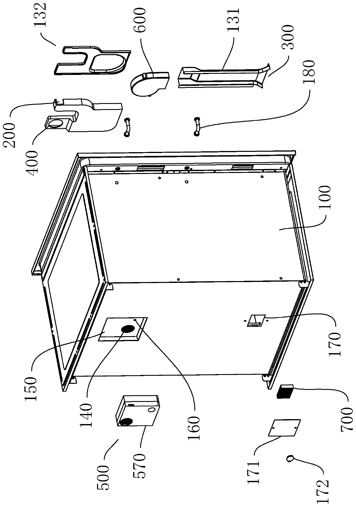
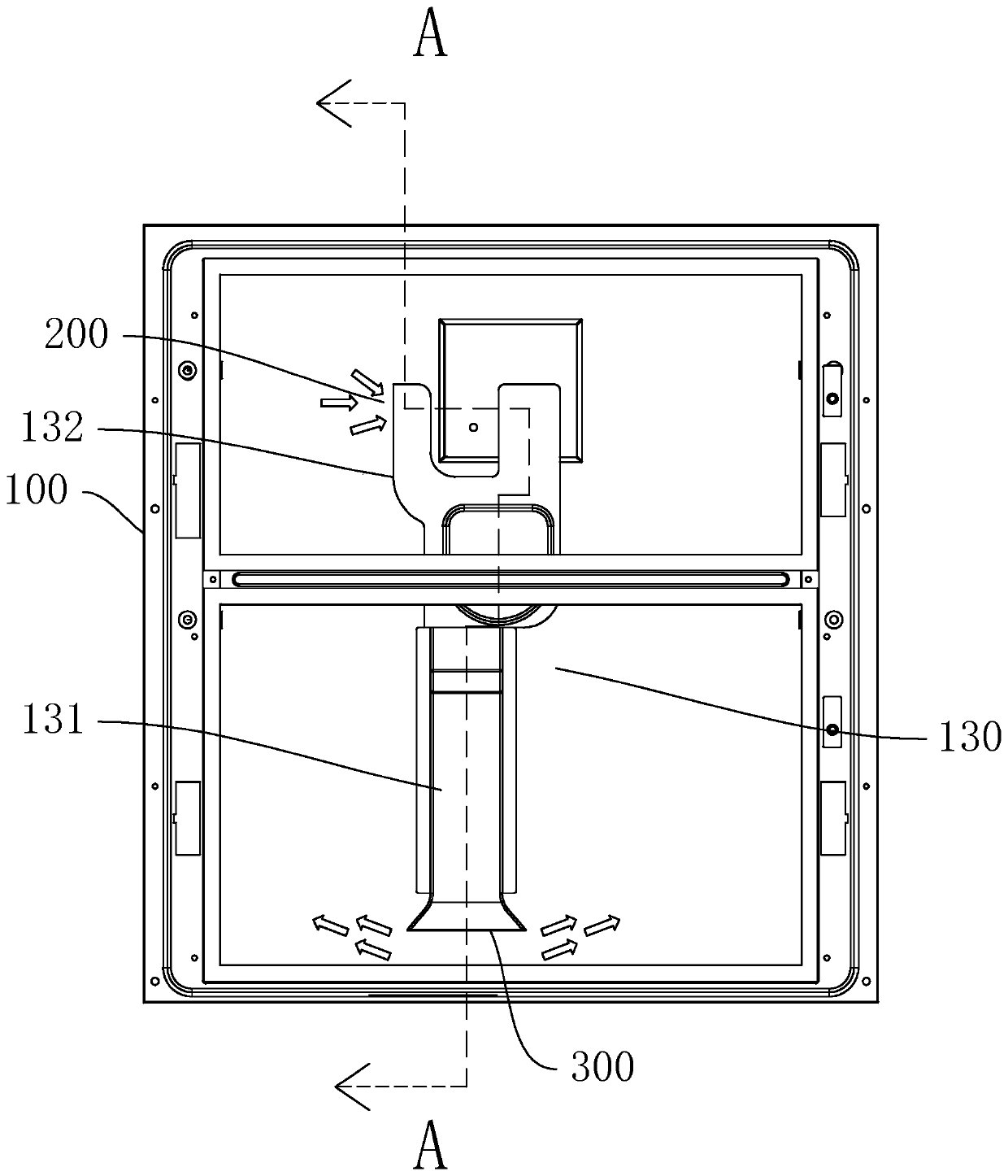
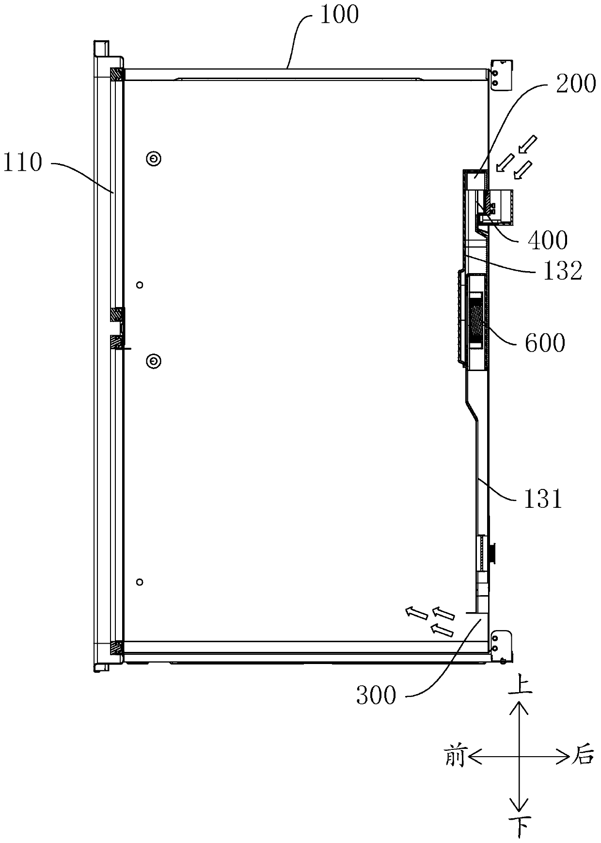
The invention discloses a disinfection cabinet with a drying function. The disinfection cabinet comprises a cabinet body, an air guide channel, an air valve assembly and a draught fan, wherein the airguide channel is provided with an air guide inlet, an air guide outlet and an air supplementing inlet; the air guide inlet and the air guide outlet communicate with the interior of the cabinet body;the air supplementing inlet communicates with the exterior of the cabinet body; the air valve assembly comprises an electric control valve body, a first humidity sensor and a second humidity sensor; the first humidity sensor is used for detecting the external air humidity of the cabinet body; the second humidity sensor is used for detecting the internal air humidity of the cabinet body; the electric control valve body comprises an electric control driving element and an air door; the electric control driving element is used for driving the air door to open or cut off communication between theair supplementing inlet and the exterior of the cabinet body; and the draught fan is used for driving air to flow in the air guide channel and the cabinet body. According to the invention, automatic starting and stopping of air supplementing are achieved; and air supplementing is effectively prevented from being conducted when the external air humidity of the cabinet body is higher than the internal air humidity of the cabinet body. The disinfection cabinet provided by the invention can be used as disinfection equipment.

Description

technical field [0001] The invention relates to a disinfection device, in particular to a disinfection cabinet with a drying function. Background technique [0002] Disinfection cabinet is a commonly used electrical product. Generally, heating components are installed inside it to realize disinfection. Because the internal air is heated and expanded, the disinfection cabinet is usually equipped with a vent hole connected to the outside to discharge hot air and control the interior safely and effectively. pressure. Since some items to be sterilized will contain moisture, during the working process of the disinfection cabinet, the moisture will vaporize, and the humidity inside the disinfection cabinet will increase. In order to speed up the drying effect, the dehumidification is achieved by introducing external air, specifically: There is an air supply air duct connected to the outside world in the disinfection cabinet, and an air valve and a fan are installed in the air sup...

Claims


Application Information

Patent Timeline
IPC IPC(8): A61L2/06A61L2/26F26B21/00B01D53/26
CPCA61L2/06A61L2/26B01D53/26B01D2257/80F26B21/001
Inventor 卢宇聪赵高航杨文国施飞
Owner GUANGDONG VANWARD ELECTRIC
Why Eureka
Try Eureka