Load box capable of satisfying net slurry inside (outside) of cylinder

A load box and cylinder technology, applied in the field of load boxes, can solve the problems of reduced final setting strength of slurry, inability to drain liquid, reduce slurry concentration, etc., and achieve the effect of increasing filling rate, ensuring strength and integrity

Pending Publication Date: 2020-07-03
江西鸿利精密制造有限公司 +1
View PDF0 Cites 0 Cited by
  • Summary
  • Abstract
  • Description
  • Claims
  • Application Information

AI Technical Summary

Problems solved by technology

[0002] In the self-balancing static load test of the foundation pile, the load box used generally has only one liquid injection pipe, so that after the test, the cylinder and the piston of the load box are filled with liquid that will never solidify, resulting in the self-balancing static load of the foundation pile. After the test, under the vertical compression state of the project, the liquid in the load box cylinder is squeezed out and the displacement occurs
[0003] Although some load tanks can realize drainage and grouting through two pipes, since the two pipes are at the same elevation on the side of the upper end of the cylinder, it is often only possible to squeeze out the liquid above the elevation of the outlet when grouting. The liquid below the level of the liquid outlet cannot be completely discharged, resulting in the dilution of the injected slurry by the retained liquid, thereby reducing the concentration of the slurry, so that the final setting strength of the slurry is seriously reduced, which cannot meet the reinforcement requirements

Method used


Image

  • Load box capable of satisfying net slurry inside (outside) of cylinder
  • Load box capable of satisfying net slurry inside (outside) of cylinder
  • Load box capable of satisfying net slurry inside (outside) of cylinder

Examples


Embodiment Construction

[0041] It should be noted that, in the following embodiments of the present invention, the orientation words are described according to the drawings, which do not constitute a limitation to the present invention.

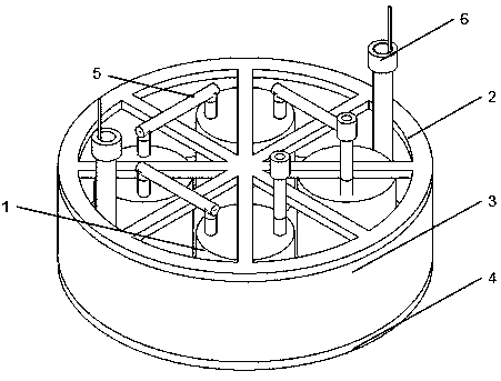
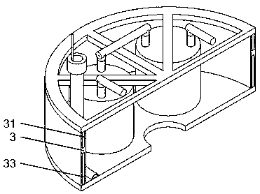
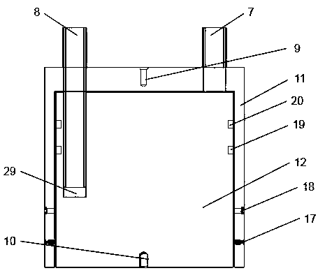
[0042] Attached below Figure 1-9 The present invention is further described in detail: a load box that satisfies the internal (outside) cleaning of the cylinder, such as Figure 1-2 As shown, it is composed of a hydraulic device 1, an upper plate 2, a waterproof connecting guard plate 3, a lower plate 4, a connecting pipe 5 and a pressure-limiting explosive grouting device 6; the hydraulic device 1 is installed between the upper plate 2 and the lower plate 3 , is multiple, connected in series through the connecting pipe 5; the upper plate 2 is a rigid lattice structure, and the waterproof connecting guard plate 3 is made of flexible waterproof material, which is H-shaped, and is movably connected with the upper plate 2 and the lower plate 4, and is pressure-limited...


PUM


Abstract

The invention relates to a load box used in a self-balancing static load test of a foundation pile, in particular to a load box capable of satisfying net slurry inside (outside) of a cylinder. The load box capable of satisfying the net slurry inside (outside) of the cylinder comprises an upper plate, a lower plate and hydraulic devices, wherein each hydraulic device comprises a liquid inlet pipe,a liquid outlet pipe, a cylinder body and a piston, the cylinder body is internally provided with a cavity, and the cavity is opened downwards; and the piston is in clearance fit with the cavity, a liquid accumulation open caisson is formed in the piston,the liquid inlet pipe penetrates through the upper surface of the cylinder body to be inserted, and the liquid outlet pipe penetrates through theupper surface of the cylinder body to be inserted into the liquid accumulation open caisson. The load box has the following advantages that 1 the slurry quality is guaranteed, and the filling rate isimproved; 2 slurry can be loaded in inside (outside) of the cylinder; 3 it is ensured that the engineering pile meets the design requirement of uplift resistance; 4 the strength and integrity of thepile body of the foundation pile are guaranteed; 5 it is ensured that the slurry outside the cylinder is high-purity net slurry; 6 an upper plate structure is convenient for laying pipelines for connecting the load boxes; and 7 the plurality of cylinder bodies are connected in series, so that integral liquid adding, liquid discharging and grouting of the load box can be realized.

Description

technical field [0001] The invention relates to a load box used in a self-balancing static load test of foundation piles, in particular to a load box satisfying the clean grout inside (outside) a cylinder. Background technique [0002] In the self-balancing static load test of the foundation pile, the load box used generally has only one liquid injection pipe, so that after the test, the cylinder and the piston of the load box are filled with liquid that will never solidify, resulting in the self-balancing static load of the foundation pile. After the test, the liquid in the load box cylinder is squeezed out and the pile is displaced under the vertical compression state of the project. [0003] Although some load tanks can realize drainage and grouting through two pipes, since the two pipes are at the same elevation on the side of the upper end of the cylinder, it is often only possible to squeeze out the liquid above the elevation of the outlet when grouting. However, the ...

Claims


Application Information

Patent Timeline
Patent Type & Authority Applications(China)
IPC IPC(8): E02D33/00
CPCE02D33/00
Inventor 钱崑陈雄陈立刚章国华
Owner 江西鸿利精密制造有限公司
Why Eureka
Try Eureka