Formwork fixing device with adjustable angle and usage method

A formwork fixing and angle-adjusting technology, which is applied to formwork/formwork components, formwork/formwork/work frame connectors, construction components on-site preparation, etc., can solve inefficiencies, inconsistent angles, low efficiency, etc. problem, achieve the effect of improving installation efficiency and easy operation

Active Publication Date: 2020-07-03
CHINA MCC17 GRP
View PDF7 Cites 2 Cited by
  • Summary
  • Abstract
  • Description
  • Claims
  • Application Information

AI Technical Summary

Problems solved by technology

[0003] In the process of foundation construction, when encountering the construction of non-vertical concrete surfaces, the traditional method is to build brick membranes, which is not only inefficient, but also the quality cannot be guaranteed
[0004] If the inclined formwork is supported, there will also be technical problems such as difficult support, angles that do not meet the design requirements, slow construction speed, and low efficiency.

Method used


Image

  • Formwork fixing device with adjustable angle and usage method
  • Formwork fixing device with adjustable angle and usage method
  • Formwork fixing device with adjustable angle and usage method

Examples


Embodiment 1

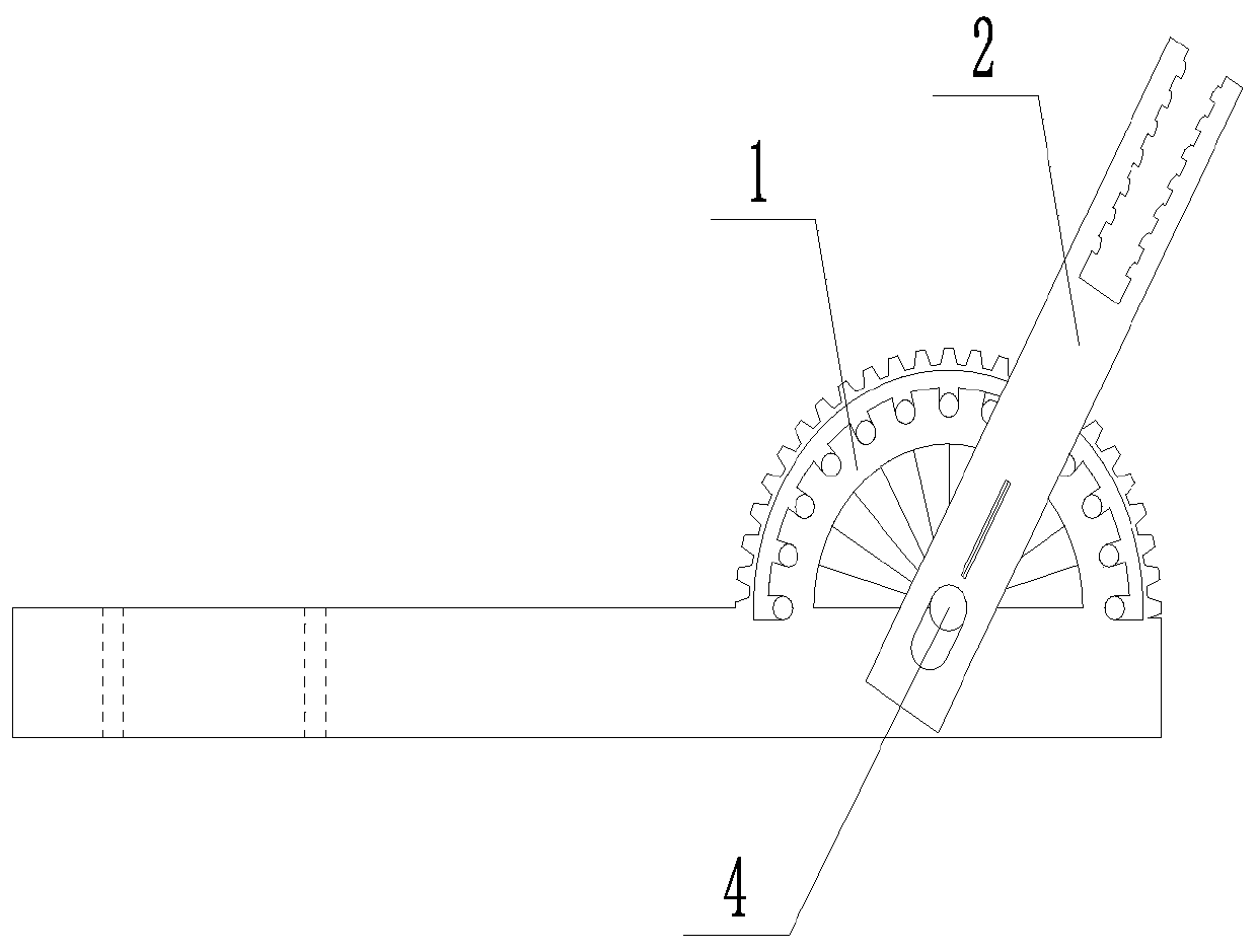
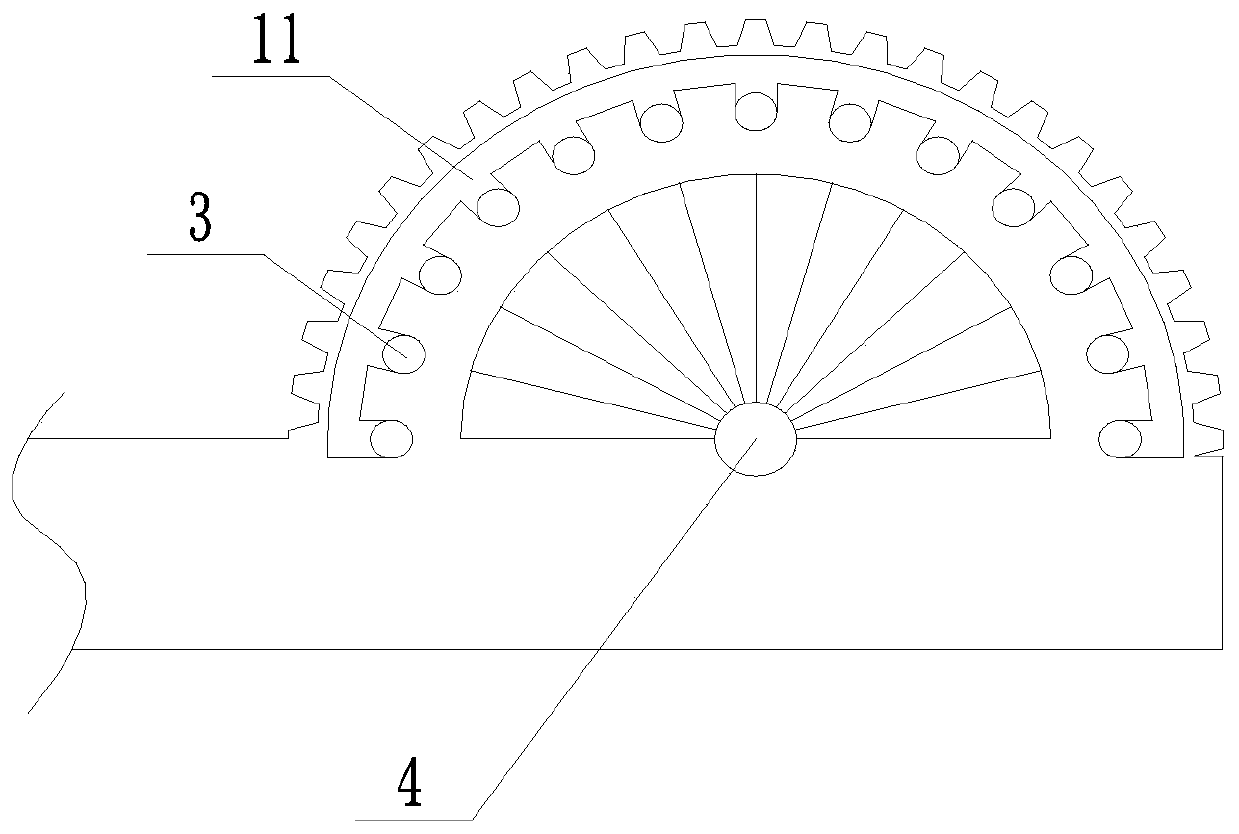
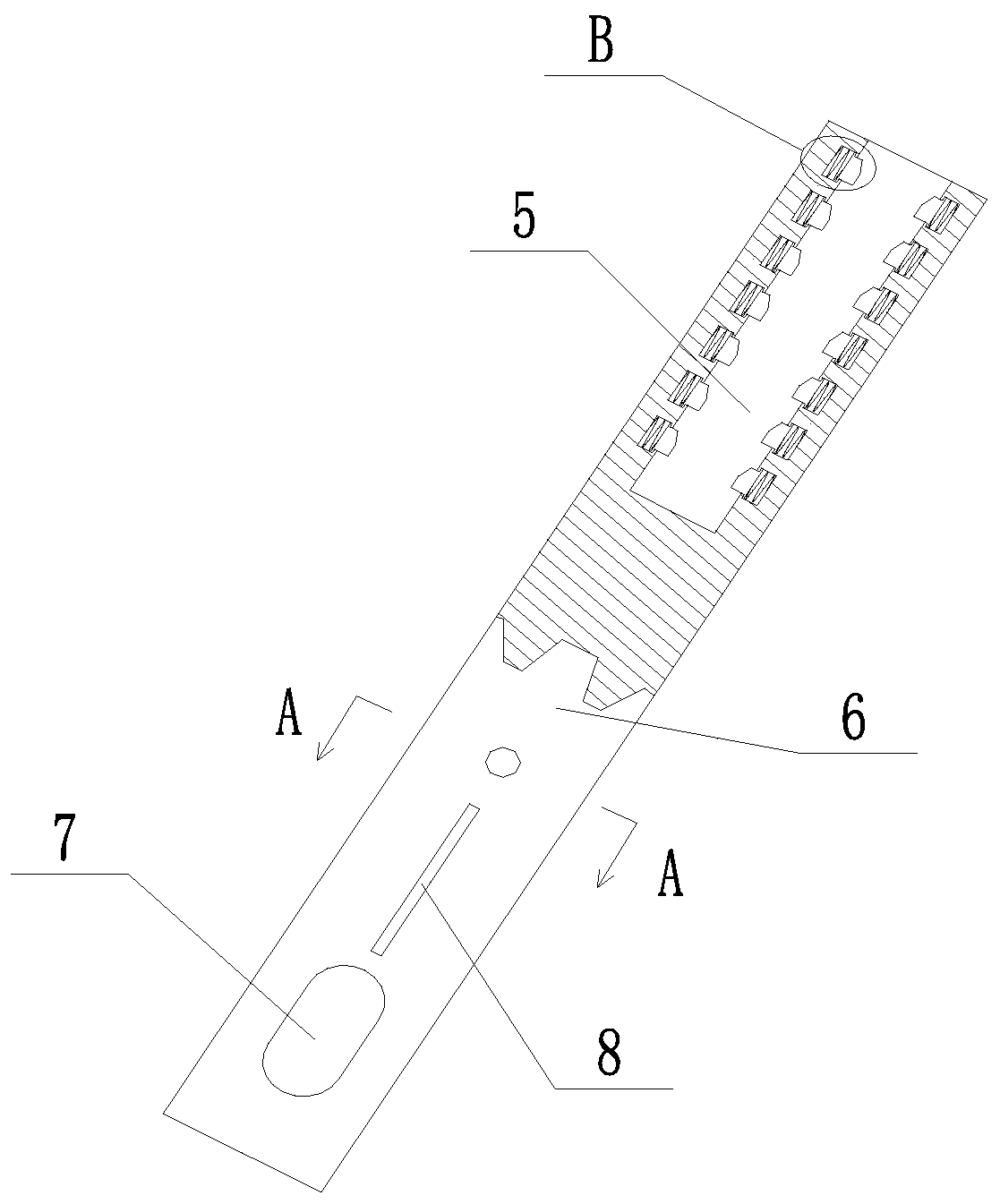
[0032] Such as Figure 1 to Figure 5 As shown, an adjustable angle template fixing device includes an angle adjuster 1 and a fixed rod 2, and the angle adjuster 1 is provided with a positioning pin 4 and a positioning blind hole 3, and several positioning blind holes 3 are provided with positioning The pin shaft 4 is evenly distributed in the center, one end of the fixed rod 2 is provided with a mounting groove 5, and the other end is provided with a limiting groove 6, the limiting groove 6 is vertically arranged with the mounting groove 5, the mounting groove 5 is used to connect the template, and the limiting groove 6 Compatible with the angle adjuster 1, the groove wall of the limit groove 6 is provided with a slotted hole 7 (the groove width of the slotted hole 7 is equal to the diameter of the positioning pin shaft 4, and the length of the slotted hole 7 is greater than the length of the positioning pin shaft 4 ), the slot hole 7 forms a sliding fit with the positioning p...

Embodiment 2

[0040] A method for using an adjustable angle template fixing device, comprising the following steps,

[0041] S1. Device installation: Fix the bolts through the installation holes on the installation base on the base layer, then insert the limit slot 6 of the fixed rod 2 on the outside of the angle adjuster 1, and pass the positioning pin shaft 4 through the limit slot 6 Fix it on the angle adjuster 1 to ensure that the positioning block 10 is compatible with the positioning blind hole 3;

[0042] S2. Pull the fixed rod 2, so that the positioning pin shaft 4 moves to the bottom along the groove wall of the slot hole 7, and at the same time, the positioning block 10 is separated from the positioning hole and moves into the track groove 11, and then the fixed rod 2 is rotated, and the fixed rod 2 uses the positioning pin The shaft 4 is the center to realize the rotation, the positioning block 10 moves in the track groove 11, observe the rotating fixed rod 2 to the desired posit...


PUM


Abstract

The invention discloses a formwork fixing device with an adjustable angle and a usage method, and belongs to the technical field of building formwork construction. An angle regulator and a fixed rod are arranged, the fixed rod is inserted on the outer side of the angle regulator through a limit groove, a groove hole and a positioning pin shaft are matched, the fixed rod is pulled when an angle requires to be adjusted, the positioning pin shaft is enabled to move to the bottom of the groove hole, at the moment, a positioning structure and a positioning blind hole realize separation, and the position of the fixed rod can be adjusted; and when the fixed rod requires to rotate, the fixed rod is rotated with the positioning pin shaft as a center, when the fixed rod is rotated to a proper position, the positioning pin shaft moves to the top of the groove hole by pushing the fixed rod, at the moment, the positioning structure and the positioning blind hole can be matched to realize the function of locking the fixed rod, then the angle adjustment is completed, the operation of construction personnel is facilitated, and the installation efficiency of a formwork is improved.

Description

technical field [0001] The invention relates to the technical field of building formwork construction, in particular to a fixing device for angle adjustment during formwork installation. Background technique [0002] With the rapid development of my country's economy, in order to maximize the use of space, urban space is accelerating towards the sky and underground. Therefore, it brings certain difficulties to the construction of buildings, and the construction of inclined concrete surfaces is one of them. [0003] In the process of foundation construction, when encountering the construction of non-vertical concrete surfaces, the traditional method is to build brick membranes, which is not only inefficient, but also the quality cannot be guaranteed. [0004] If the inclined formwork is supported, there will also be technical problems such as difficult support, angles that do not meet the design requirements, slow construction speed, and low efficiency. Contents of the inve...

Claims


Application Information

Patent Timeline
Patent Type & Authority Applications(China)
IPC IPC(8): E04G9/02E04G17/00
CPCE04G9/02E04G17/00
Inventor 康鸿
Owner CHINA MCC17 GRP
Why Eureka
Try Eureka