
Three-degree-of-freedom decomposition mooring structure measurement experiment device

An experimental device and a technology of degrees of freedom, applied in the direction of measuring device, machine/structural component testing, fluid dynamics test, etc., can solve the problem of high experimental cost, etc., and achieve the effect of reasonable device design and simple structure

Active Publication Date: 2020-07-03
SUN YAT SEN UNIV
View PDF11 Cites 8 Cited by
  • Summary
  • Abstract
  • Description
  • Claims
  • Application Information

AI Technical Summary

Problems solved by technology

At present, most of the model mooring experiments are to determine the mooring conditions through preliminary estimation, and the cost of the experiment is relatively high.

Method used


Image

  • Three-degree-of-freedom decomposition mooring structure measurement experiment device
  • Three-degree-of-freedom decomposition mooring structure measurement experiment device
  • Three-degree-of-freedom decomposition mooring structure measurement experiment device

Examples


Embodiment 1

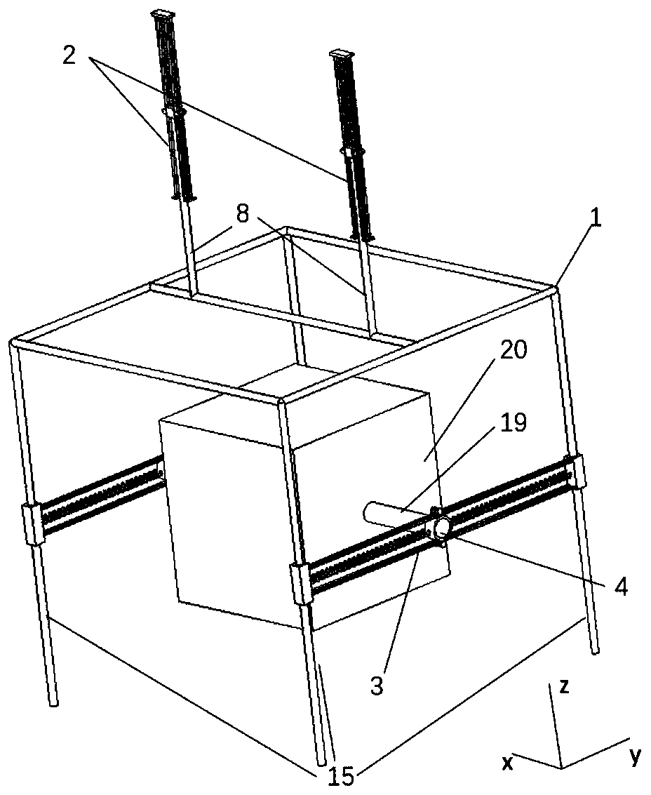
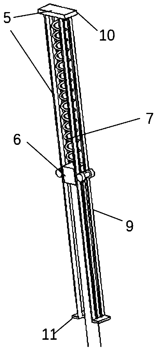
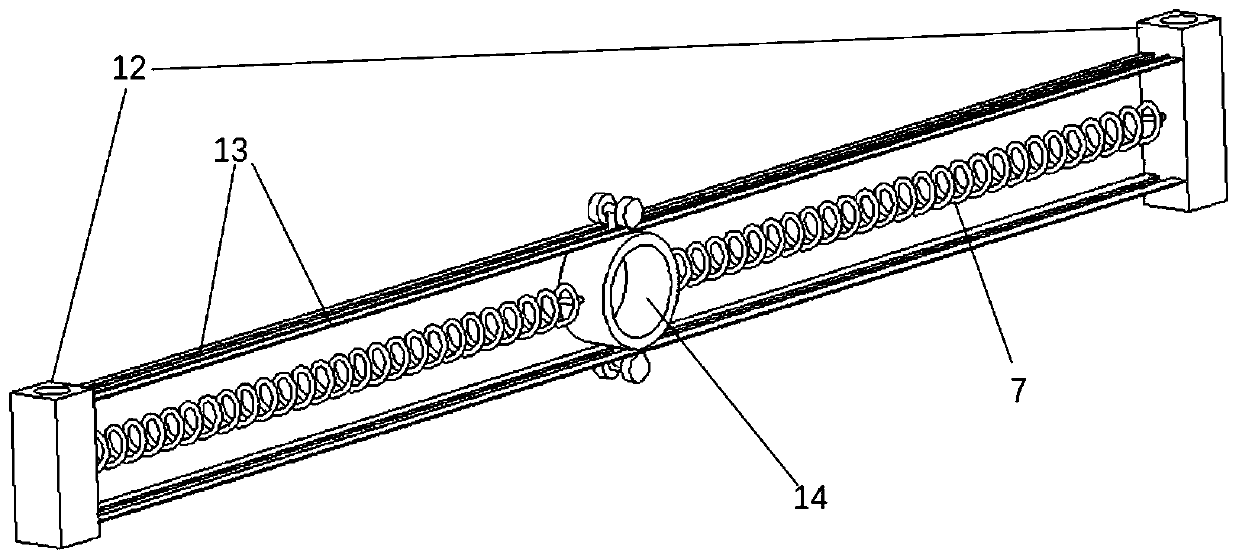
[0035] Such as figure 1As shown, a three-degree-of-freedom decomposition mooring structure measurement experiment device includes a device frame 1, a Z-direction measurement system 2, a Y-direction measurement system 3, and an X-direction rotation measurement system 4. The water flow direction is set as the y-axis, perpendicular to The upward direction of the water surface is set as the z-axis, the x-axis is perpendicular to the y-axis and the z-axis, and the x-axis, y-axis and z-axis form a right-handed coordinate system. The right-handed coordinate system is one of the methods for specifying a rectangular coordinate system in space. The positive directions of the x-axis, y-axis and z-axis in this coordinate system are specified as follows: put the right hand at the origin, make the thumb, index finger and middle finger at right angles to each other, point the thumb to the positive direction of the x-axis, and the index finger When pointing to the positive direction of the y...

Embodiment 2

[0052] Such as Image 6 As shown, the difference between Embodiment 2 and Embodiment 1 is that the mooring mechanism 23 is selected to be installed on the second straight rod 15 extending downwards from the device frame 1, and the tension and pressure sensing device in the device frame 1 7 is replaced by a displacement sensor 21, and the object 20 to be measured is moored on the mooring mechanism 23 through a cable, and the mooring force of the object 20 to be measured in the experiment is measured with the tension pressure sensor on the mooring cable, and at the same time, it is measured through the X rotation direction The system 4, the Y-direction measurement system 3 and the Z-direction measurement system 2, obtains the corresponding three degrees of freedom motion response of the object to be measured 20 under the mooring condition.

[0053] In this embodiment, the mooring mechanism 23 and the device frame 1 can move relatively, so that the device frame 1 can be displaced...


PUM


Abstract

The invention relates to the technical field of measurement experiment equipment, and more specifically relates to a three-degree-of-freedom decomposition mooring structure measurement experiment device. The device comprises a device frame, a Z-direction measurement system, a Y-direction measurement system and an X-direction rotation measurement system, wherein the water flow direction is set to be a y axis, the upward direction perpendicular to the water surface direction is set to be a z axis, the x axis is perpendicular to the y axis and the z axis, and the x axis, the y axis and the z axisform a right-hand coordinate system. Under the action of waves, the device frame and the to-be-measured object move up and down along the z-axis, and the to-be-measured object moves back and forth along the y-axis and rotates along the x-axis. The device is reasonable in design and simple in structure, and can effectively measure the three-degree-of-freedom motion and dynamic response of the to-be-measured object.

Description

technical field [0001] The invention relates to the technical field of measurement experiment equipment, and more specifically, to a measurement experiment device for three-degree-of-freedom decomposition mooring structures. Background technique [0002] There are six main forms of movement of ships or offshore structures such as buoys, cages, floating breakwaters, etc.: roll, pitch, yaw, heave, sway, surge. Among them, rolling is the most likely to occur, and the influence of structures is the greatest. In extreme cases, it may even cause structural damage. Most of the current model test equipment simulates the sloshing state of the structure through some mechanical structures, which are somewhat different from the waves in the real state. Therefore, it is necessary to design a multi-degree-of-freedom measurement system applicable to the real wave state Solve practical problems and study experimentally the mechanisms that generate kinematic coupling. Ships or offshore st...

Claims


Application Information

Patent Timeline
IPC IPC(8): G01M10/00
CPCG01M10/00
Inventor 胡文清李熠华詹杰民范庆苏炜汪林飞
Owner SUN YAT SEN UNIV
Learn More