Multi-span simply-supported boundary condition test device

A technology of boundary conditions and test devices, applied in the direction of measuring devices, testing of mechanical components, testing of machine/structural components, etc., can solve problems such as the inability to adjust the support position, and achieve scientific research funding, strong versatility, and low cost Effect

Inactive Publication Date: 2020-07-03
HARBIN ENG UNIV
View PDF2 Cites 0 Cited by
  • Summary
  • Abstract
  • Description
  • Claims
  • Application Information

AI Technical Summary

Problems solved by technology

[0003] In order to solve the problem that the support position of the existing beam and plate simply supported boundary condition experimental device cannot be adjusted, and the simply supported beam (slab) of different sizes cannot be realized, the present invention further provides a multi-span simply supported boundary condition Test device

Method used


Image

  • Multi-span simply-supported boundary condition test device
  • Multi-span simply-supported boundary condition test device
  • Multi-span simply-supported boundary condition test device

Examples


specific Embodiment approach 1

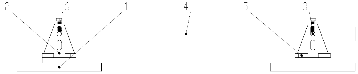
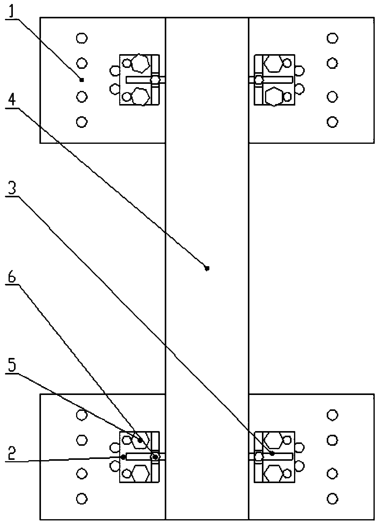
[0025] Specific implementation mode one: combine Figure 1 to Figure 7 Describe this embodiment, a multi-span simply supported boundary condition test device described in this embodiment includes a plurality of base plates 1, a test beam 4 and a plurality of support assemblies, a plurality of base plates 1 are arranged side by side along a straight line, and each base plate 1 is installed For one support assembly, the test beam 4 is horizontally installed on multiple support assemblies.

specific Embodiment approach 2

[0026] Specific implementation mode two: combination Figure 4 Describe this embodiment, each support assembly described in this embodiment includes two L-shaped supports 2, round rods 3, fixing bolts 5 and compression bolts 6, and the two L-shaped supports are installed symmetrically along the length direction of the bottom plate 1 , the transverse plate 2-1 of each L-shaped support 2 is fixedly connected to the bottom plate 1 through the fixing bolt 5, the round bar passes through the thicker test beam horizontally, and the two ends of the round bar pass through two holes on both sides of the test beam respectively. The strip hole in the vertical plate of the L-shaped support is used to fix the hold-down bolt 6 of the round bar 3 to be installed in the threaded hole at the upper end of the vertical plate 2-2. For thicker test beams, simple support can be realized by perforating holes on the test beams to cooperate with round rods 3 . Other components and connections are the...

specific Embodiment approach 3

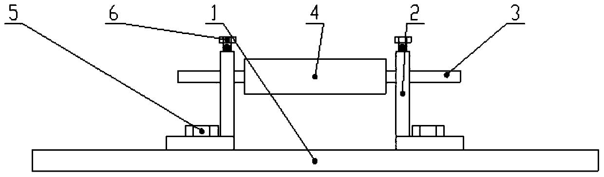
[0027] Specific implementation mode three: combination Figure 5 Describe this embodiment, each support assembly described in this embodiment includes two L-shaped supports 2, two round rods 3, fixing bolts 5 and compression bolts 6, and the two L-shaped supports are along the length direction of the bottom plate 1 Symmetrical installation, the horizontal plate 2-1 of each L-shaped support 2 is fixedly connected with the bottom plate 1 through the fixing bolt 5, and the two ends of the round rod 3 pass through the two vertical plates 2-2 on both sides of the test beam 4 respectively. Long holes, and two round rods 3 are stacked up and down, the test beam 4 is located between the two round rods 3 and between the two L-shaped supports 2, and the compression bolts 6 for fixing the round rods 3 are installed In the threaded hole on the vertical plate 2-2 upper end, screw in the bolt to achieve the purpose of compressing the round bar.

[0028] That is: for thinner beams (slabs), ...


PUM


Abstract

The invention discloses a multi-span simply-supported boundary condition test device, relates to a supporting test device and aims to solve problems that the support position of an existing beam and plate simple support boundary condition experiment device cannot be adjusted, and that beams (plates) with different sizes cannot be simply supported in the prior art. The device comprises a pluralityof bottom plates, a cross beam and a plurality of supporting assemblies, wherein the bottom plates are arranged side by side along a straight line, one supporting assembly is installed on each bottomplate, and a test beam is horizontally installed on the supporting assemblies. The invention belongs to the technical field of mechanical test devices. The device is advantaged in that simple supporting of beams (plates) with different widths and lengths can be achieved, cost is low, universality is high, and the scientific research expenditure of related experiments can be saved.

Description

technical field [0001] The invention relates to a mechanical test support device, in particular to a multi-span simply supported boundary condition test device, which belongs to the technical field of mechanical test devices. Background technique [0002] In scientific research and engineering practice, in addition to using theoretical analysis methods, the research on the static and dynamic characteristics of specific beam and slab structures often requires experimental verification to ensure the accuracy and reliability of the analyzed structure. Whether the experimental conditions are reasonable and whether the theoretical analysis assumptions are satisfied greatly affect the accuracy of the experimental results. The support position of the existing experimental devices for simply supported boundary conditions of beams and plates cannot be adjusted, and simply supported beams (slabs) of different sizes cannot be realized, which affects the efficiency of experimental resea...

Claims


Application Information

Patent Timeline
Patent Type & Authority Applications(China)
IPC IPC(8): G01M13/00
CPCG01M13/00
Inventor 杜绍君李凤明柴玉阳
Owner HARBIN ENG UNIV
Why Eureka
Try Eureka