Method for measuring the film element using optical multi-wavelength interferometry

a multi-wavelength interferometry and film element technology, applied in the field of film measurement, can solve the problems of t use both spectral phases, t have anti-vibration ability, and the ellipsometer cannot measure the 2-dimeional thickness and optical constants of thin film

Inactive Publication Date: 2012-06-07
NAT CENT UNIV
View PDF7 Cites 12 Cited by
  • Summary
  • Abstract
  • Description
  • Claims
  • Application Information

AI Technical Summary

Benefits of technology

[0008]A method for optical measuring the film element using multi-wavelength interferometry is revealed. This invention use reflection coefficients of thin films at different wavelengths to measure the thickness and optical constants of thin films. The tested thin film sample was measured in an optical interferometer. The white light is separated in different wavelength in measurements by narrow band-pass filter or dispersive elements. The phase difference coming from the reflection phase difference between test and reference surfaces is distinguished from the phase difference coming from the spatial path difference between reference and test beams by doing measurements on different wavelengt

Problems solved by technology

However, the ellipsometer can not measure the 2-dimeional thickness and optical constants of thin film; the surface profile of the substrate and the residual stress cannot be known by the ellips

Method used


Image

  • Method for measuring the film element using optical multi-wavelength interferometry
  • Method for measuring the film element using optical multi-wavelength interferometry
  • Method for measuring the film element using optical multi-wavelength interferometry

Examples


Embodiment Construction

[0014]The present invention will be apparent from the following detailed description, which proceeds with reference to the accompanying drawings, wherein the same references relate to the same elements.

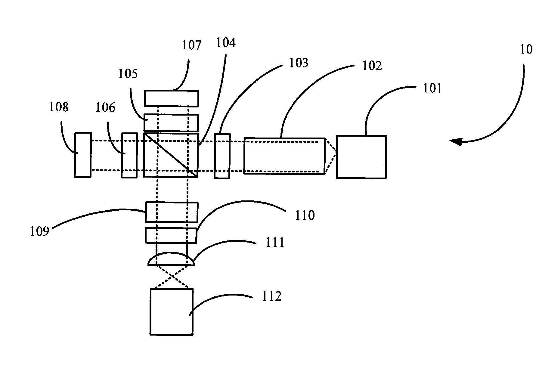
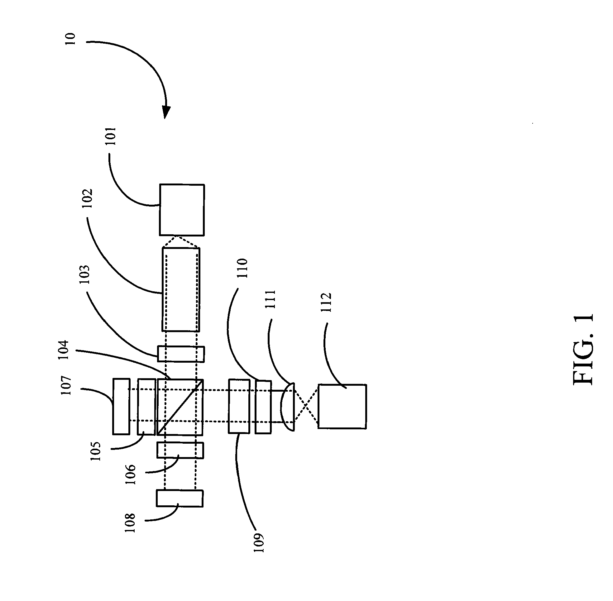
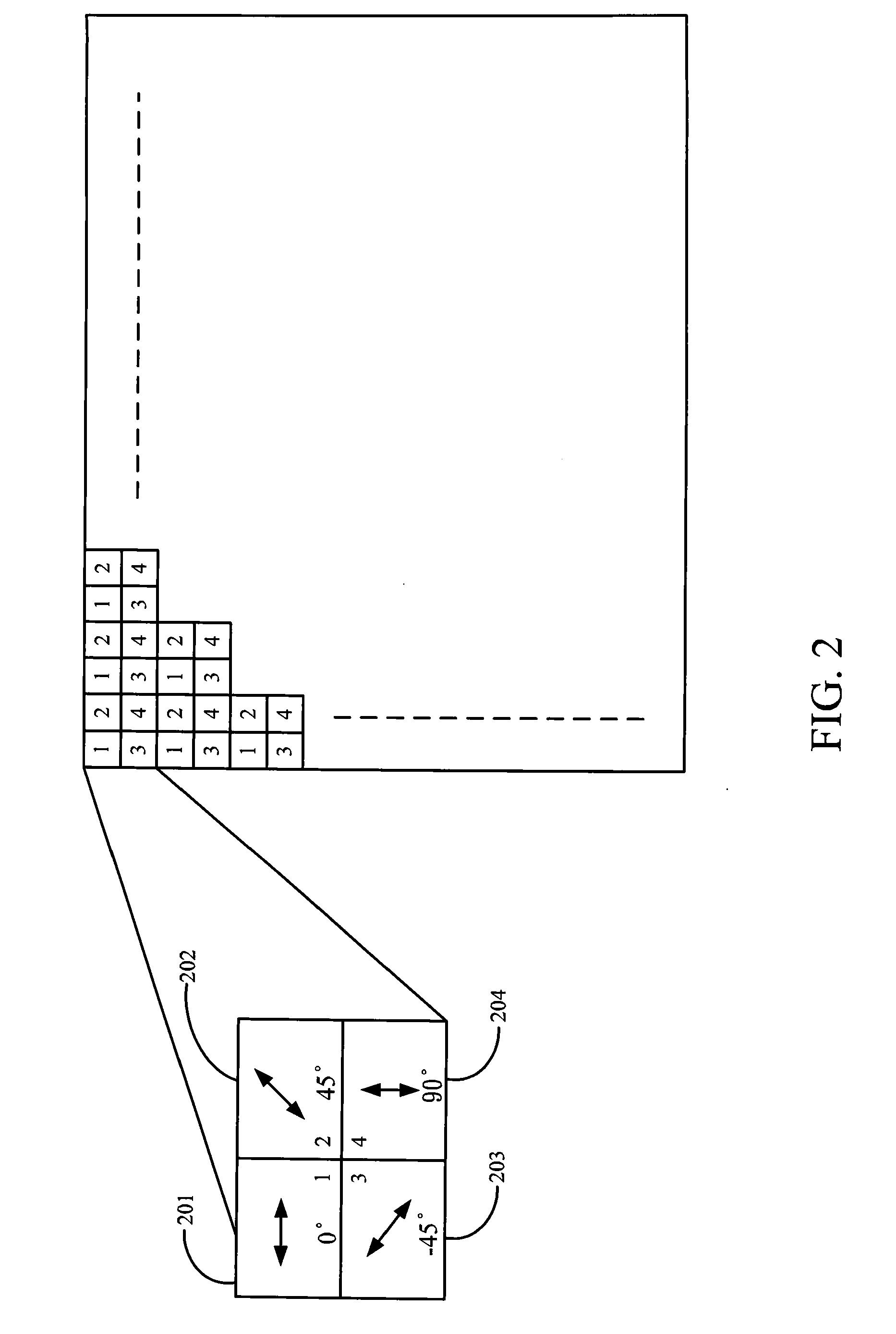
[0015]In this invention, both magnitude and phase of reflection coefficient of thin films are acquired in a dynamic white light interferometer, which is composed of an optical polarization interferometer and a pixelated phase mask camera to obtain the optical constants and thickness of the thin films with vibration and air turbulence resistance.

[0016]The phase measured in an interferometer is the phase difference between the reference and test beams. It is composed of two parts: spatial path length difference and reflection phase difference between the reference surface and thin film surface. Multi-wavelength measurements of phase and intensity are used to separate these two parts, because they all change in different ways when measuring wavelength changes.

[0017]Referring to FIG. 1, a...


PUM


Abstract

A method for measuring the film element using optical multi-wavelength interferometry is revealed. The invention uses reflection coefficients of thin films at different wavelengths to measure the thickness and optical constants of thin films. The phase difference coming from the phase difference between test and reference surfaces is distinguished from the phase difference from the spatial path difference between reference and test beams by doing measurements on different wavelengths, because they change in different ways as the measuring wavelength changes. The phase is then acquired. Combining with the measured reflectance of thin film, the reflection coefficient of thin film is obtained. Collecting the reflection coefficients of each point, the thin film thickness and optical constants distribution in 2 dimensions are calculated. The surface profile is known through the spatial path differences between reference and test beams. These can be measured in a interferometer to avoid the vibration influence.

Description

BACKGROUND OF THE INVENTION[0001]1. Field of Invention[0002]The present invention relates to a method for measuring film and, in particular, to a method for measuring the film element using optical multi-wavelength interferometry.[0003]2. Related Art[0004]Non-contact photometry transmission and reflection intensity spectrum are generally used to learn the optical constants and thickness of thin films today. But the measurements accuracy and precision are lower than ellipsometer measurements, especially in multilayer film stack measurement, since ellipsometry measurements measure both coatings' reflection magnitude and phase at the same time to increase the precision of the answers. However, the ellipsometer can not measure the 2-dimeional thickness and optical constants of thin film; the surface profile of the substrate and the residual stress cannot be known by the ellipsomter.[0005]Recent researches used measured reflection magnitude spectra to calculate the thickness and refracti...

Claims


Application Information

Patent Timeline
IPC IPC(8): G01B9/02
CPCG01B11/0675
Inventor LEE, CHENG-CHUNGWU, KAI
Owner NAT CENT UNIV
Why Eureka
Try Eureka