
Device for amplifying a laser beam with suppression of transverse lasing

a laser beam and transverse lasing technology, applied in the direction of laser cooling arrangements, laser details, active medium shape and construction, etc., can solve the problems of high cost, toxic, dangerous use, and particularly troublesome transverse lasing, so as to increase the number of interfaces and therefore the number of reflections, the effect of preventing parasitic lasing

Active Publication Date: 2015-12-08
THALES SA
View PDF13 Cites 2 Cited by
  • Summary
  • Abstract
  • Description
  • Claims
  • Application Information

AI Technical Summary

Benefits of technology

The invention is a solution to prevent parasitic lasing in a laser system by using a structure that increases losses. This allows for efficient removal of thermal power through water cooling. The invention includes a crystal with a specific geometric structure that increases reflections and interfaces, and an absorbent liquid with a high heat capacity to dissipate the thermal power. The invention also utilizes angles to avoid total internal reflection and allows for a density or element absorbent at the same wavelength as the amplifying bar structure. The technical effects of the invention are improved laser efficiency, reduced parasitic lasing, and improved thermal management.

Problems solved by technology

This transverse lasing is particularly troublesome in the case of solid amplifying media with high gains and of large dimensions (typically a gain g0 of 0.88 and a pump diameter of 70 mm).
This liquid is moreover very corrosive.
It is furthermore expensive and toxic and therefore dangerous to use; it deteriorates over time.

Method used


Image

  • Device for amplifying a laser beam with suppression of transverse lasing
  • Device for amplifying a laser beam with suppression of transverse lasing
  • Device for amplifying a laser beam with suppression of transverse lasing

Examples


Embodiment Construction

[0041]Hereinafter, an amplifying bar made of crystal is taken as an example. It can be replaced with doped glass such as for example phosphate glass or silicate glass doped with Neodymium ions or Ytterbium ions.

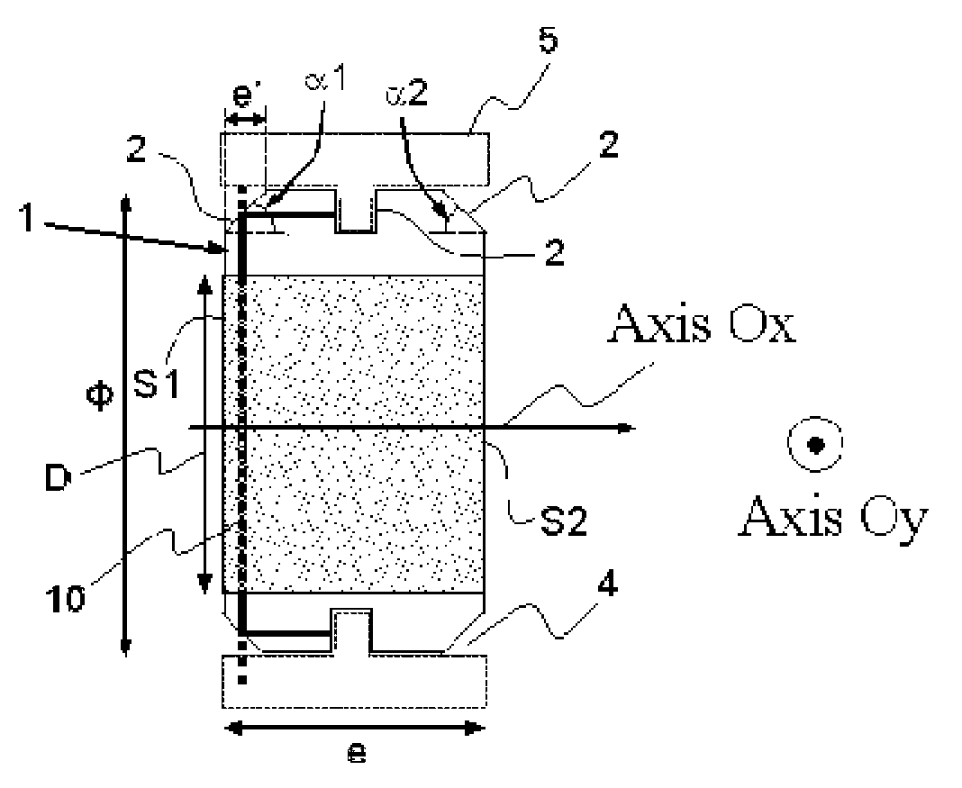
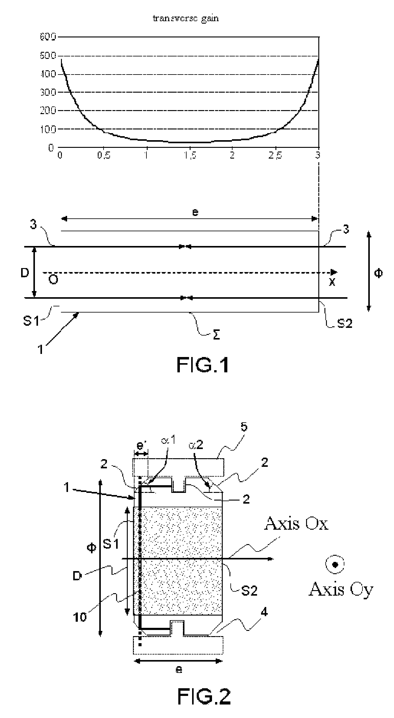
[0042]FIG. 2 shows a crystal structure 1 with a single crystal, whose geometry is modified by adding “teeth”2 to the surface Σ, which are so many new interfaces on which the photons are in part reflected, the other part being absorbed or scattered.

[0043]The angle α of each tooth with respect to the axis Ox is optimized to avoid total internal reflection inside the crystal, since the aim is for part of the photons to be transmitted. We therefore want:

sin(α)nA / nc,with nA<nc

nc being the index of the crystal, nA the index of the liquid A forming with the crystal this interface.

[0044]Accordingly, it is possible to modify the angle α and / or the index nA.

[0045]It is furthermore necessary that the photons transmitted do not return: it is therefore necessary that they be absorbed ...


PUM


Abstract

A device for amplifying a laser beam along an axis comprises: an amplifying bar structure of index nc, delimited by a surface connecting the input and output faces of the structure, having a dimension e along the axis and Φ along a perpendicular direction, with e<Φ, and intended to be pumped to become a gain medium with a maximum along a face, and a liquid of index nA which surrounds the structure in relation to its surface and which is absorbent or scattering at the fluorescence wavelength of the amplifying bar structure. The surface comprises a first tooth in the form of a chamfer at its junction with the maximum gain face, to avoid causing parasitic transverse lasing and the liquid of index nA has a heat capacity of greater than 3000 Joules per kilogram per K° to dissipate the thermal power induced by the pumping.

Description

CROSS-REFERENCE TO RELATED APPLICATIONS[0001]This application is a National Stage of International patent application PCT / EP2011 / 062385, filed on Jul. 19, 2011, which claims priority to foreign French patent application No. FR 1003042, filed on Jul. 20, 2010, the disclosures of which are incorporated by reference in their entirety.FIELD OF THE INVENTION[0002]The field of the invention is that of the amplification of a laser beam and more particularly that of amplifying bars.BACKGROUND[0003]The manner of operation of a laser beam amplification device is briefly recalled. It mainly comprises an amplifying medium and pumping sources which inject energy into the amplifying medium. This amplifying medium which has the shape of a bar may be a crystal, or else a doped glass. Thereafter, the laser beam to be amplified traverses the amplifying bar one or more times by means of optical devices with mirrors for example; on each pass it extracts a part of the energy injected during the pumping ...

Claims


Application Information

Patent Timeline
Patent Type & Authority Patents(United States)
IPC IPC(8): H01S3/10H01S3/06H01S3/04H01S3/08H01S3/0941
CPCH01S3/10H01S3/0615H01S3/0407H01S3/061H01S3/0604H01S3/0606H01S3/0612H01S3/0617H01S3/08018H01S3/09415H01S2301/02H01S3/06H01S3/0941H01S3/04H01S3/08
Inventor BRANLY, STEPHANEDERYCKE, CHRISTOPHELAUX, SEBASTIEN
Owner THALES SA
Learn More