
Process and arrangement for superimposing ray bundles

a technology of superimposing rays and bundles, applied in the direction of beam/ray focussing/reflecting arrangements, instruments, electric discharge lamps, etc., can solve the problem of no longer optimal polarisation conditions for reflection, and achieve the effect of minimising radiation loss

Inactive Publication Date: 2006-03-30
MYOS MY OPTICAL SYSTEM GMBH
View PDF6 Cites 46 Cited by
  • Summary
  • Abstract
  • Description
  • Claims
  • Application Information

AI Technical Summary

Benefits of technology

[0021] The object of the present invention is to configure a process and an arrangement of the type mentioned in the introduction so that the danger of damaging individual light sources due to radiation reflected at the workpiece is reduced.
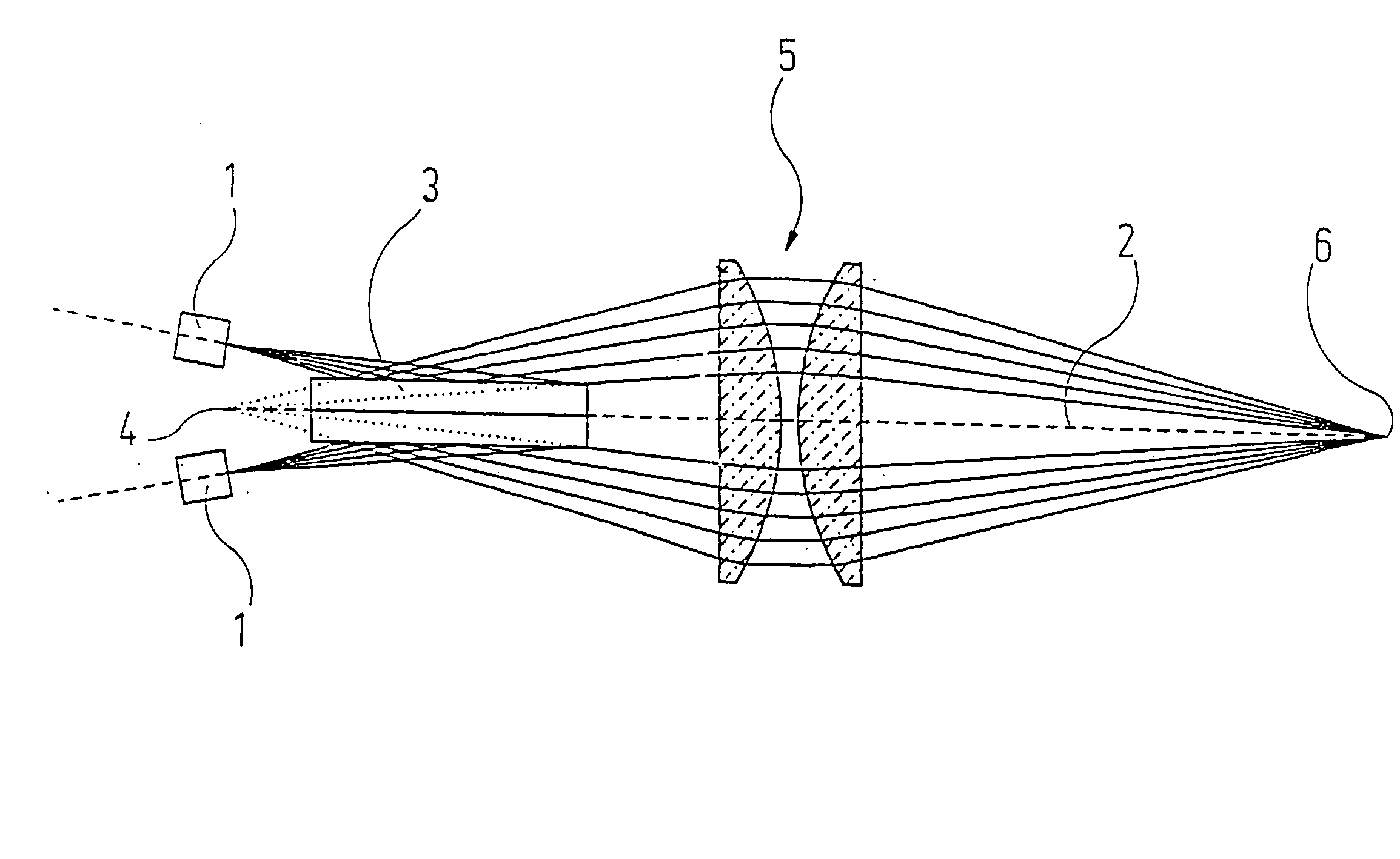
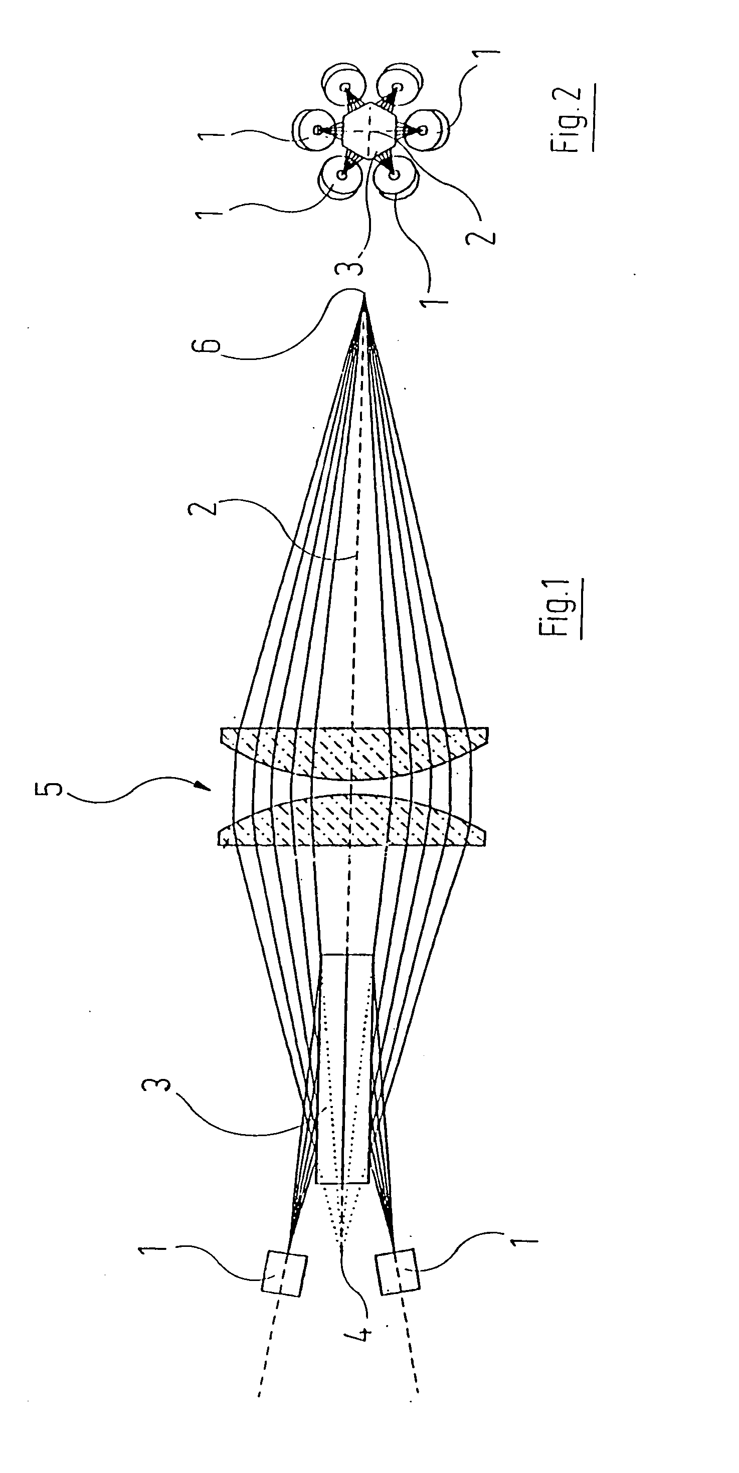
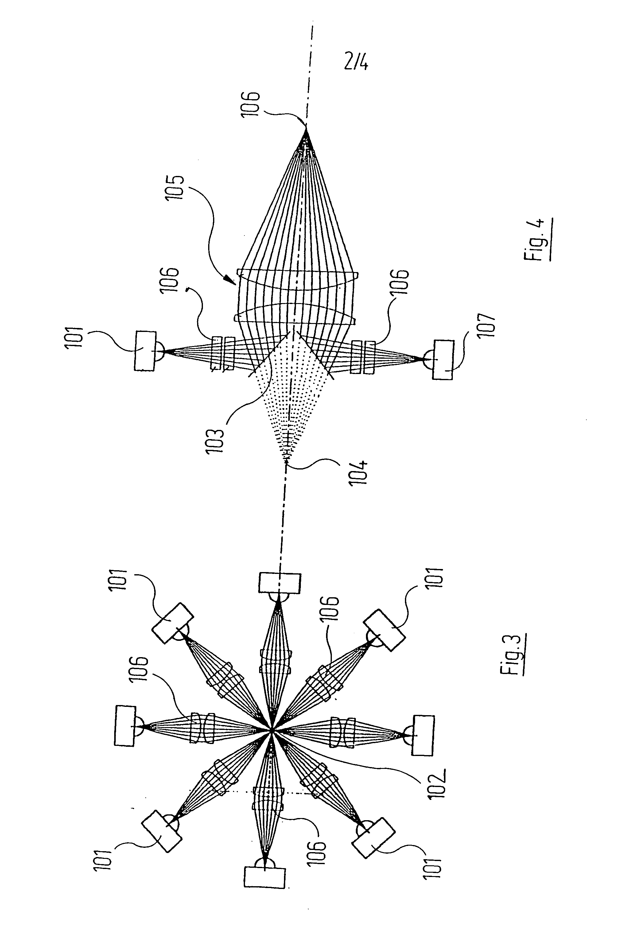
[0022] This object, as regards the process, is solved by the fact that the individual ray bundles are polarised substantially linearly and are reflected in their path to the superimposition point at least at a surface whose reflection capability is polarisation-dependent, wherein the polarisation direction of the radiation coming from the individual radiation sources is aligned so that the first reflection at the surface takes place with low loss, whereas a second reflection, after preceding reflection at the workpiece, takes place with high loss.
[0024] The aforementioned object is, as regards the arrangement, solved by the fact that a) a reflecting surface whose reflection capability is polarisation-dependent is arranged in the ray path of each ray bundle; b) the ray bundles are in each case polarised substantially linearly, wherein c) the direction of polarisation is aligned so that the first reflection of the ray bundles coming from the individual radiation sources takes place with low loss, whereas a second reflection after a preceding reflection at the workpiece takes place with high loss.
[0028] The angle of incidence of the ray bundles coming from the individual radiation sources on the reflecting surface should be chosen so that a total reflection takes place. In this way radiation losses are minimised.

Problems solved by technology

If this elliptically polarised back radiation now arrives a second time at one of the reflecting surfaces, then the polarisation conditions for the reflection are no longer optimal; however, a very small proportion of the radiation is reflected in the direction of an individual radiation source, which is thereby no longer threatened.

Method used


Image

  • Process and arrangement for superimposing ray bundles
  • Process and arrangement for superimposing ray bundles
  • Process and arrangement for superimposing ray bundles

Examples


Embodiment Construction

[0037] While the present invention is capable of embodiment in many different forms, there is shown in the drawings and will herein be described in detail, preferred embodiments of the invention with the understanding that the present disclosure is to be considered as an exemplification of the principles of the invention and is not intended to limit the broad aspect of the invention to the embodiments illustrated.

[0038] Reference will first of all be made to FIGS. 1 and 2. The arrangement illustrated here may be used in particular for marking purposes on workpieces. The arrangement includes six individual emitters, in the present case individual laser diodes 1, which are arranged at the same angular spacing of in each case 60° with respect to one another on a circle around the optical axis 2 of the arrangement. Each individual emitter 1 emits substantially linearly polarised light that is as far as possible spatially coherent. The better the coherence, the better the beam quality a...


PUM


Abstract

A process and an arrangement are described by means of which a plurality of ray bundles emitted from individual radiation sources are combined with the aid of an imaging optics system. The individual radiation sources are in this connection arranged on at least one curve surrounding the optical axis of the imaging optics system. The individual ray bundles are substantially linearly polarised. The bundles are reflected on their path to the superimposition point at least at a surface whose reflection capability is polarisation-dependent. The polarisation direction of the ray bundles coming from the individual radiation sources is in this connection aligned so that the first reflection at the surface takes place with low loss, whereas a possible second reflection after previous reflection at the workpiece takes place with high loss. In this way the individual radiation sources are protected against damaging back-reflections.

Description

RELATED APPLICATION [0001] This patent application claims the benefit of the filing date of German patent application no. DE 10 2004 045 912.6, filed Sep. 20, 2004. BACKGROUND OF THE INVENTION [0002] The present invention relates to a process for superimposing ray bundles that are emitted by a plurality of individual radiation sources and are combined with the aid of a ray forming and focussing optics system, in which the individual radiation sources are arranged on at least one curve surrounding the optical axis of the ray forming and focusing optics system, as well as an arrangement for superimposing ray bundles that are emitted by a plurality of individual radiation sources, with a ray forming and focusing optics system that combines the ray bundles at a superimposition point, in which the individual radiation sources are arranged on at least one curve surrounding the optical axis of the ray forming and focusing optics system. [0003] Such processes and arrangements are used in ca...

Claims


Application Information

Patent Timeline
IPC IPC(8): H01J3/14
CPCG02B27/0905
Inventor JURCA, MARIUS CHRISTIAN
Owner MYOS MY OPTICAL SYSTEM GMBH
Learn More