
Detection method

a technology of absorption spectroscopy and apparatus, which is applied in the field of apparatus and methods for absorption spectroscopy of cavity, can solve the problems of increasing complexity of dispensing and detection operations, increasing the cost of detection, and increasing the length of the gas phase base path, so as to facilitate efficient, yet inexpensive, detection, and low detection volume

Active Publication Date: 2012-12-04
UNIV OF TEESSIDE
View PDF9 Cites 5 Cited by
  • Summary
  • Abstract
  • Description
  • Claims
  • Application Information

AI Technical Summary

Benefits of technology

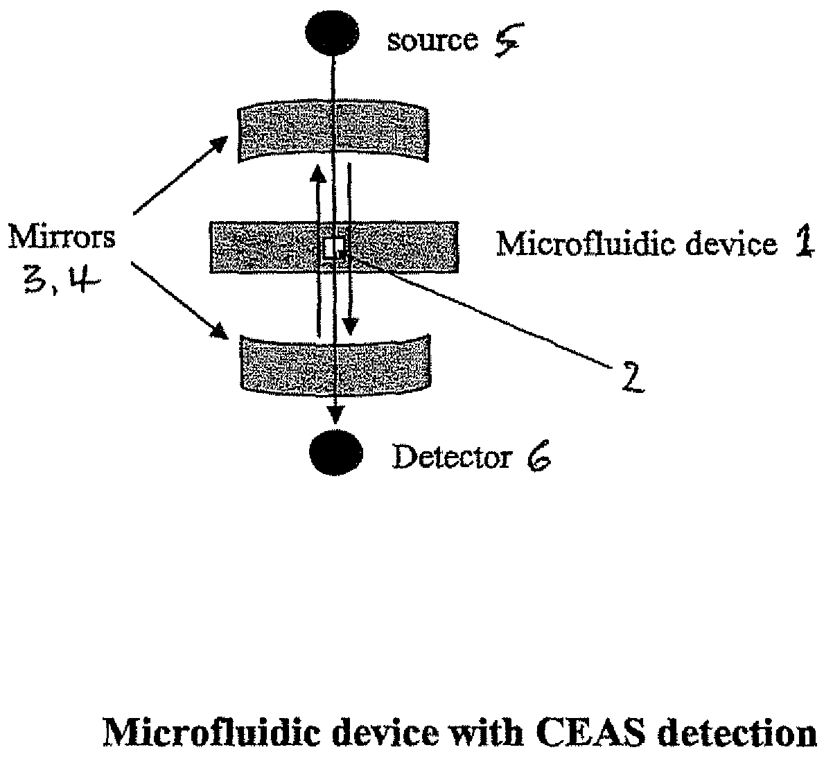
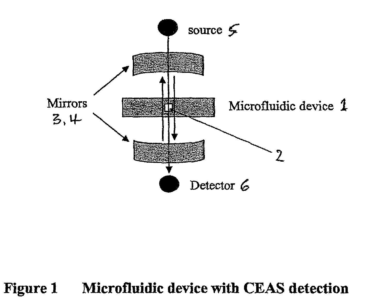
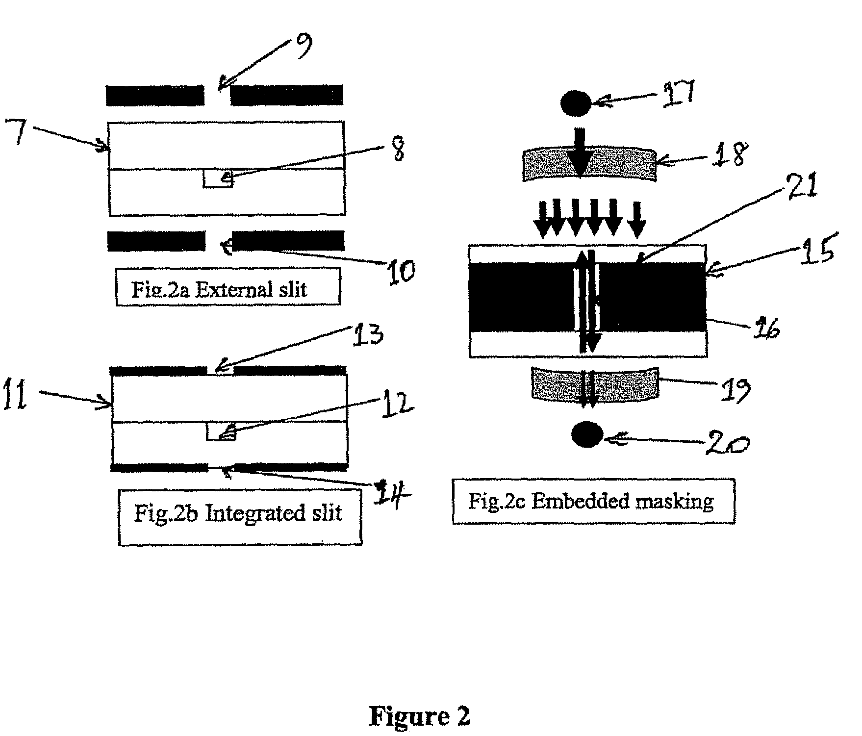
[0027]Radiation losses may occur, for example as a result of absorption by elements of the microfluidic device, or by scattering therefrom. However, such losses may be minimised by various means including, for example, the use of at least one slit through which the radiation is caused to pass. The slit may be located externally from the microfluidic device or may be integrated onto the outer walls of said device. Alternatively, the losses may be minimised by the use of at least one masking element which is preferably embedded as part of the microfluidic device. In an alternative embodiment, radiation losses are minimised by the use of additional mirrors, which may be deposited on the side walls of the microfluidic device.
[0028]According to a second aspect of the present invention, there is provided a method for the detection of the spectral absorption properties of a fluid in a microenvironment, said method comprising exposing a fluid contained in a microfluidic device to radiation, causing said radiation to pass through said fluid, and detecting said radiation after its passage through said fluid, wherein said method is performed in an apparatus which comprises means for increasing the path length of said radiation through said fluid.
[0030]The present invention thus uses the CEAS method for detection in microfluidic devices, including active and passive devices. Such microfluidic devices allow complex processing through respectively their architecture and robotic control. However, since these types of devices have low detection volumes, highly sensitive methods of detection are required. The use of CEAS, rather than CRDS, in microfluidic devices facilitates efficient, yet inexpensive, detection. The CRDS method would be significantly more expensive, since it requires a compromise between path length and fast detection; given that the path length for microfluidic devices is inherently small, expensive fast detection systems would be required.

Problems solved by technology

Increasing the density of micro-well plates provides some advantages in evaporation losses of the liquid, but also leads to increasing complexity in operations such as dispensing and detection.
Specifically, absorbance methods can be applied by measuring across either the channel length or the channel width of a microfluidic device but, in view of the short path length in microfluidic devices, such techniques have the disadvantage of relatively low sensitivity in comparison to macroscopic devices.
These methods rely on light being confined between two highly reflective mirrors, thereby resulting in the base path length being increased by many orders of magnitude in the gas phase.
However, the detection of the light exiting the cavity requires fast response detectors and associated equipment capable of measuring on the nanosecond timescale and this consideration, along with the expense of pulsed laser sources, makes most implementations of CRDS prohibitively expensive and inconvenient.
Unfortunately, however, a further consequence is that the absorption cross section now cannot be measured directly and, instead, a comparison with a reference compound in the cavity is firstly required.
There is an associated disadvantage, however, which is typically manifested as a lower wavelength resolution for the absorption spectrum.
Furthermore, the disclosed method is only relevant for measurements relating to gaseous systems.
However, each of these approaches only allows the fluid to pass through the optical cavity, and there is no potential for the fluid to interact with a functionalised surface, or for the performance of complex micro and nanoscale volume fluidic operations, such as the mixing, direction and separation of reagent and sample streams in an integrated approach.
Therefore, the existing techniques would be difficult to miniaturise for application to very small scale situations and also would not readily facilitate the creation of large numbers of devices (potentially thousands to millions).

Method used


Image

  • Detection method
  • Detection method
  • Detection method

Examples


Embodiment Construction

[0041]The invention provides a method and apparatus which allow for the detection of the spectral absorption properties of a fluid in a microenvironment by means of Cavity Enhanced Absorption Spectroscopy. The microenvironment may comprise a microfluidic device comprising at least one microchannel formed in a substrate through which the fluid may flow, allowing for measurements to be taken on a continuous basis; such microfluidic devices are generally referred to as a Lab-on-a-chip. Typically, the overall section of said microchannels may be anything from about 1 μm2 to about 1 mm2, thereby providing mirror separations in the micrometre and sub millimetre ranges. In certain preferred embodiments of the invention, mirror separations are generally in the range from about 10 μm to about 100 μm.

[0042]The mirror separations employed in the method and apparatus of the present invention allow for accurate measurements to be obtained by the use of sample volumes which are significantly lowe...


PUM

PropertyMeasurementUnit
volumeaaaaaaaaaa
volumeaaaaaaaaaa
diameteraaaaaaaaaa

Abstract

The invention relates to an apparatus and method for the detection of the spectral absorption properties of a fluid in a microenvironment, the apparatus comprising a radiation source, a microfluidic device and detection means, wherein the apparatus additionally comprises means for increasing the path length of the radiation through the fluid. Preferably, the means for increasing the path length of the radiation through the fluid comprises two highly reflective mirrors which cause the base path length through the fluid to be increased by many orders of magnitude, and the method comprises Cavity Enhanced Absorption Spectroscopy. The method is especially useful for the handling of small volumes of fluids for chemical and biological processing.

Description

CROSS REFERENCE TO RELATED APPLICATIONS[0001]This is the national stage of International Application No. PCT / GB2007 / 050734, filed on Dec. 3, 2007, which claims the benefit of Great Britain Application No. 0624148.3, filed on Dec. 2, 2006, the contents of all of which are incorporated herein by reference.FIELD OF THE INVENTION[0002]The present invention is concerned with an apparatus and method for the determination of the absorption features of small volumes of fluids contained in microenvironments. More specifically, the invention relates to apparatus and methods for Cavity Enhanced Absorption Spectroscopy (CEAS) detection in microfluidic devices.BACKGROUND OF THE INVENTION[0003]A number of sectors of technology require greater exploration of both chemical and biological space and diversity. In the pharmaceutical sector, for example, the search for new drug candidate compounds is leading to compounds being made and screened at an ever increasing rate. The resulting increase in dema...

Claims


Application Information

Patent Timeline
Patent Type & Authority Patents(United States)
IPC IPC(8): G01N21/00
CPCB01L3/502715G01N21/031G01N21/39B01L2300/0654B01L2300/0816B01L2300/168B01L2400/0406B01L2400/0409B01L2400/0415B01L2400/0487B33Y80/00
Inventor ALI, ZULFIQURSEETOHUL, LALITESH NITINAUGER, VINCENT DAVIDISLAM, MEEZANULSCOTT, SIMON MICHAEL
Owner UNIV OF TEESSIDE
Learn More