
Electronic pulse generator and oscillator

a pulse generator and oscillator technology, applied in the direction of generating/distributing signals, pulse techniques, instruments, etc., to achieve the effect of high losses

Inactive Publication Date: 2003-08-14
ANALOG DEVICES INC
View PDF12 Cites 50 Cited by
  • Summary
  • Abstract
  • Description
  • Claims
  • Application Information

AI Technical Summary

Benefits of technology

[0016] minimising cross-conduction, say by selecting between early and late signals
[0022] arranging paralleled paths of current carrying conductors to reduce inductive differences between connecting or intersection positions
[0025] tracking to equalise each wave magnetically and improve current skewing
[0028] using receive signal conductors and transmission return-current lines during transmit, thus avoiding need for separate ground trace
[0030] multiphase transmission to avoid ground bounce problems including to where only one line is switching at any one time.

Problems solved by technology

Also, the termination and reflection problems of conventional H-tree signal distribution do not apply; and there are predictable phases / phase relationships at all points (coherency), so clear practicality for moving away from the single-phase synchronous paradigm and its very high power spikes.

Method used


Image

  • Electronic pulse generator and oscillator
  • Electronic pulse generator and oscillator
  • Electronic pulse generator and oscillator

Examples


Embodiment Construction

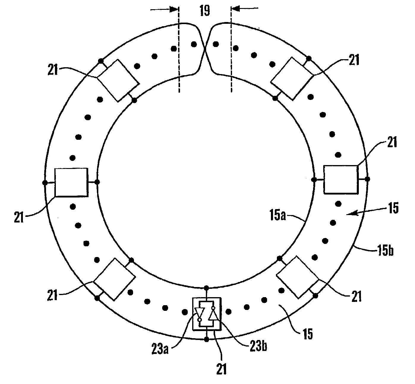
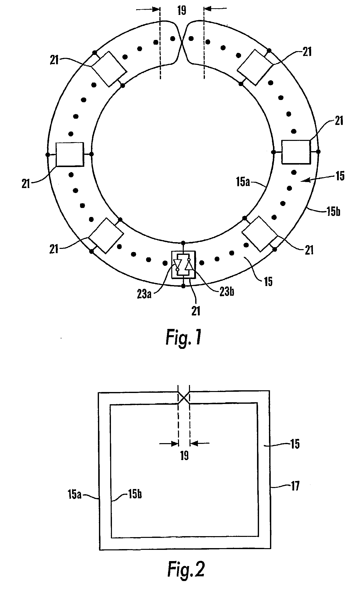
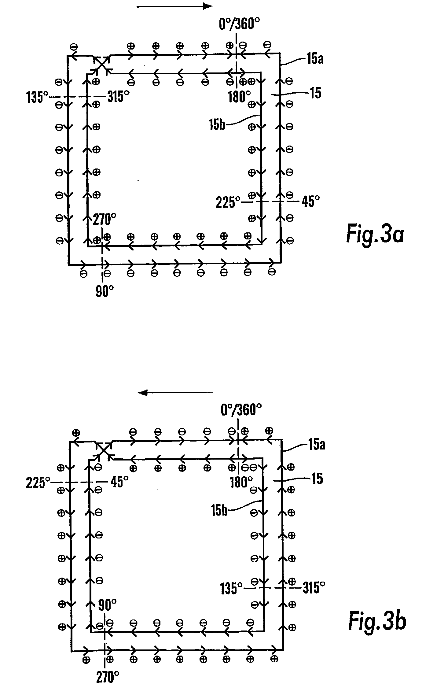
[0070] FIG. 1 shows a transmission-line 15 as a structure that is physically as well as electromagnetically endless, specifically comprising a single continuous "originating" conductor formation 17 shown forming two appropriately spaced generally parallel traces as loops 15a, 15b with a cross-over at 19 that does not involve any local electrical connection of the conductor 17. The length of the originating conductor 17, taken as S, corresponds to two `laps` of the transmission-line 15 as defined between the spaced loop traces 15a, 15b and through the cross-over 19. The cross-over 19 produces a Moebius strip effect where edge traces of the loops 15a, 15b invert from lap to lap.

[0071] As a pulse generator, actually an oscillator, the transmission-line 15 has associated plural spaced active means 21 conveniently of bi-directional switching / amplifying nature shown as two inverters 23a, 23b connected back-to-back between the conductive loop traces 15a, 15b. Alternative active regenerativ...


PUM


Abstract

Improvements in and relating to electronic pulse generation or oscillation circuitry based on a signal path exhibiting endless electromagnetic continuity and affording signal phase inversion in setting pulse duration or half-cycles of oscillation within time of signal traverse of said signal path, and having active switching means associated with said signal path to set rise and fall times of each said pulse or said half-cycle of oscillation, including for frequency adjustment by selective inductance and power saving without stopping pulse generation or oscillation.

Description

[0001] This invention concerns improvements in and relating to electronic production and use of repeating cyclic pulse signals having a repetition rate related to electrical signal path length(s).BACKGROUND TO INVENTION[0002] Co-pending international patent application PCT / GB00 / 00175 (published WO 00 / 44093) has the same inventor as this application, and relates to such electronic signal production. Suitable disclosed electronic circuitry includes composite electromagnetic / semiconductor structures for providing timing signals in integrated circuits (ICs), typically in clocking digital ICs, including VLSI (very large scale integrated) circuits. Uniquely such provisions have no physical distinction between signal operation means and signal distribution means, those functions now being merged in the same physical means.[0003] Structurally, suitable such means includes at least one signal path exhibiting endless electromagnetic continuity and affording signal phase inversion of an electr...

Claims


Application Information

Patent Timeline
Patent Type & Authority Applications(United States)
IPC IPC(8): H03K3/03H03K3/86
CPCH03B5/1852H01L2924/0002H01L2924/00
Inventor WOOD, JOHN
Owner ANALOG DEVICES INC
Learn More