
Surface acoustic wave device

a surface acoustic wave and acoustic wave technology, applied in piezoelectric/electrostrictive/magnetostrictive devices, piezoelectric/electrostriction/magnetostriction machines, electrical equipment, etc., can solve the problem of inability to obtain sufficient characteristics as surface acoustic wave resonators and/or surface acoustic wave filters, disadvantageous deformation of insertion loss, etc. problem, to achiev

Active Publication Date: 2011-04-12
MURATA MFG CO LTD
View PDF16 Cites 2 Cited by
  • Summary
  • Abstract
  • Description
  • Claims
  • Application Information

AI Technical Summary

Benefits of technology

The solution effectively suppresses spurious responses, maintains high reflection coefficients, and improves frequency temperature characteristics by optimizing the film thickness and Euler angles of the IDT electrode and SiO2 layer, leading to superior resonant and filter characteristics.

Problems solved by technology

Accordingly, because of irregularities formed by the steps described above, an insertion loss is disadvantageously degraded.
On the other hand, when the IDT electrode is formed from Al, it has been known that a reflection coefficient of the IDT electrode considerably decreases, and hence sufficient characteristics as a surface acoustic wave resonator and / or a surface acoustic wave filter cannot be obtained.

Method used


Image

  • Surface acoustic wave device
  • Surface acoustic wave device
  • Surface acoustic wave device

Examples


Embodiment Construction

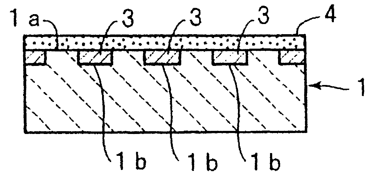
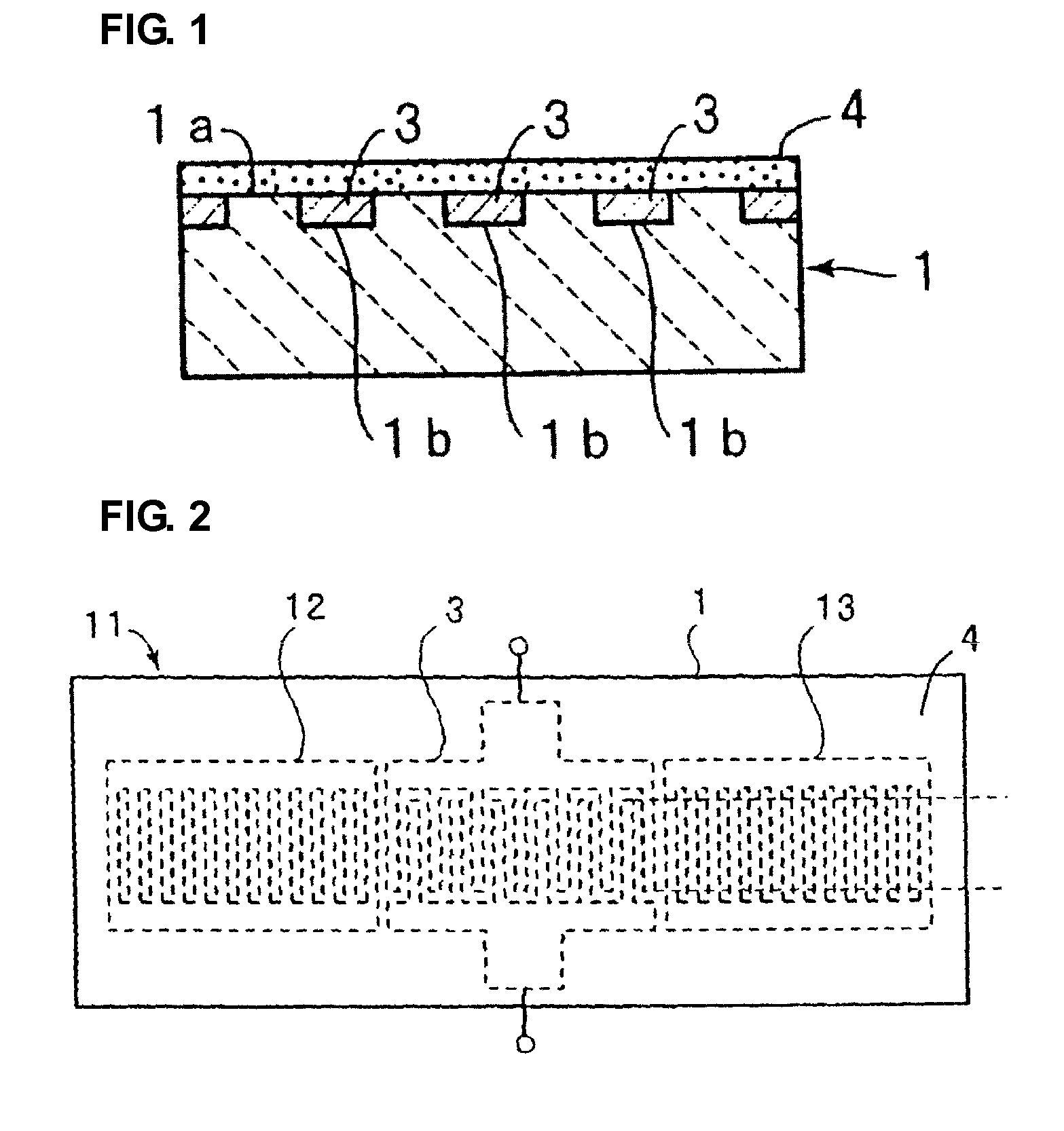
[0052]FIG. 1 is a schematic front cross-sectional view of a surface acoustic wave device according to one preferred embodiment of the present invention, and FIG. 2 is a schematic plan view of the surface acoustic wave device according to this preferred embodiment.

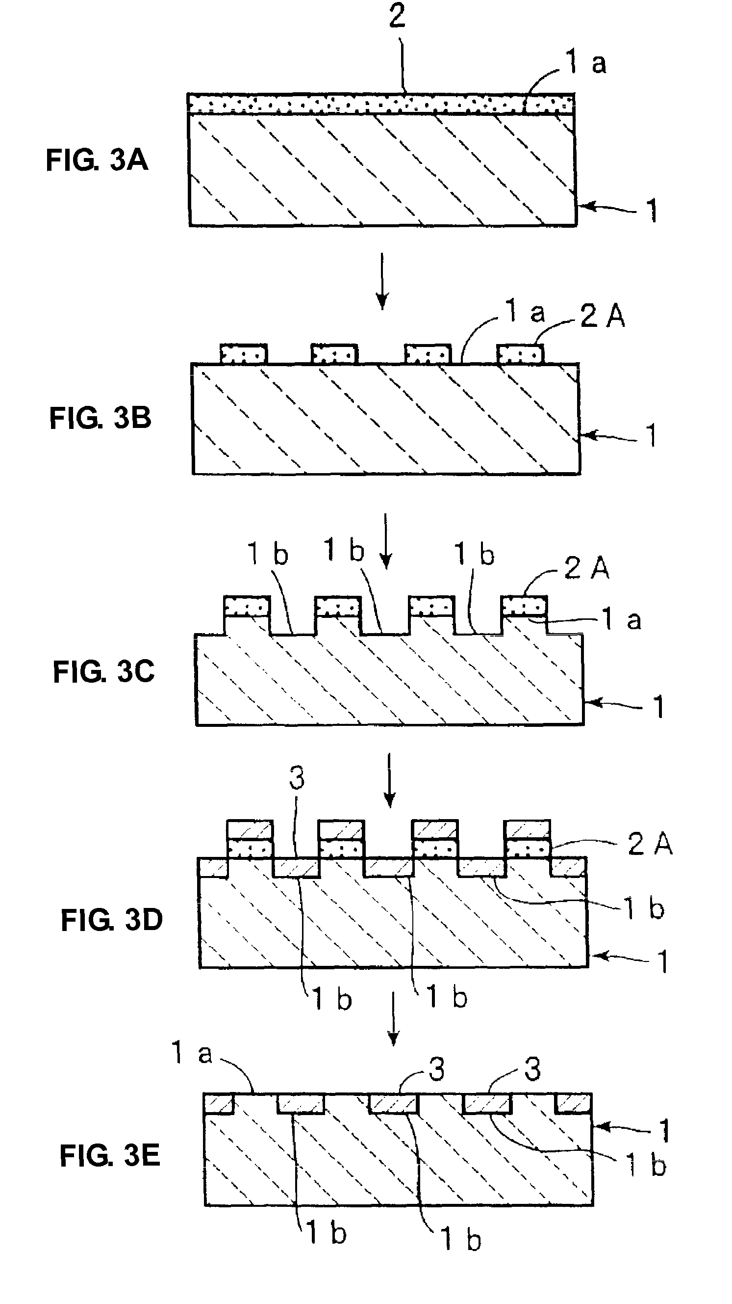
[0053]As shown in FIG. 2, a surface acoustic wave device 11 has a LiNbO3 substrate 1. In an upper surface 1a of this LiNbO3 substrate 1, a plurality of grooves 1b is provided and arranged as shown in FIG. 1. An IDT electrode 3 is defined by a metal filled in the grooves 1b.

[0054]That is, the IDT electrode 3 is defined by a metal primarily composed of Pt embedded in the grooves 1b so that the upper surface 1a of the LiNbO3 substrate 1 and an upper surface of the IDT electrode 3 are flush with each other.

[0055]As shown in FIG. 2, at two sides of the IDT electrode 3 in a direction of surface acoustic wave propagation, reflectors 12 and 13 are disposed. As in the case of the IDT electrode 3, the reflectors 12 and 13 are also p...


PUM


Abstract

A surface acoustic wave device including an SiO film has improved frequency temperature characteristics, prevents an increase in insertion loss, obtains a reflection coefficient of an electrode that is sufficiently high, and achieves more preferable resonant characteristics and filter characteristics. The surface acoustic wave device includes a LiNbO3 substrate having a plurality of grooves formed in an upper surface thereof, an IDT electrode primarily composed of Pt provided in the grooves, a SiO2 layer arranged so as to cover the upper surface of the LiNbO3 substrate and the IDT electrode, a surface of the SiO2 layer is planarized, a response of a Rayleigh wave is utilized, and Euler angles of the LiNbO3 substrate are in a range of (0°±5°, 208° to 228°, 0°±5°).

Description

BACKGROUND OF THE INVENTION[0001]1. Field of the Invention[0002]The present invention relates to a surface acoustic wave device in which a SiO2 film is laminated so as to cover a piezoelectric substrate and an IDT electrode. Particularly, the present invention relates to a surface acoustic wave device in which an IDT electrode is composed of a metal filled in grooves located in an upper surface of a piezoelectric substrate.[0003]2. Description of the Related Art[0004]A duplexer (DPX) or an RF filter used for a mobile communication system, such as a mobile phone, is required to have both wide band characteristics and superior temperature characteristics. Previously, a surface acoustic wave device has been widely used as a DPX or an RF filter.[0005]In particular, for the application described above, a surface acoustic wave device in which an IDT electrode is formed on a piezoelectric substrate of LiTaO3 or LiNbO3 has been widely used. LiTaO3 and LiNbO3 each have a negative temperature...

Claims


Application Information

Patent Timeline
Patent Type & Authority Patents(United States)
IPC IPC(8): H03H9/25H01L41/047H10N30/87
CPCH03H9/02559H03H9/14538
Inventor KIMURA, TETSUYAKADOTA, MICHIOYAOI, MARI
Owner MURATA MFG CO LTD
Learn More