Lighting device

a technology of light source and light source, which is applied in the direction of auxillary/base layers of photosensitive materials, instruments, photosensitive materials, etc., can solve the problems of increasing energy consumption, affecting the efficiency of light generation, and a substantial fraction of light generated does not exit the intended decoupling surface, so as to achieve the effect of improving efficiency

Active Publication Date: 2012-05-08
OSRAM OPTO SEMICONDUCTORS GMBH
View PDF26 Cites 2 Cited by
  • Summary
  • Abstract
  • Description
  • Claims
  • Application Information

AI Technical Summary

Benefits of technology

[0009]It is the object of the present invention to create a lighting device of the aforesaid kind whose efficiency is improved. In particular, according to the invention, more than about half the light generated by the light source is decoupled direct

Problems solved by technology

Incoherent light sources, however—such as LED chips, for example—have a much more complex radiation characteristic that makes it much more difficult to adapt the optical element.
With such lighting devices, however, it can happen that a substantial fraction of the light generated does not exit from the intended decoupl

Method used


Image

  • Lighting device
  • Lighting device
  • Lighting device

Examples


Embodiment Construction

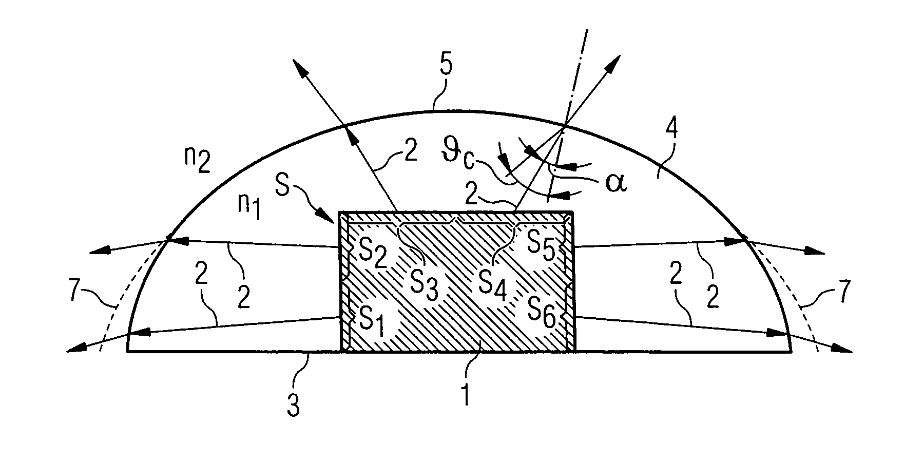
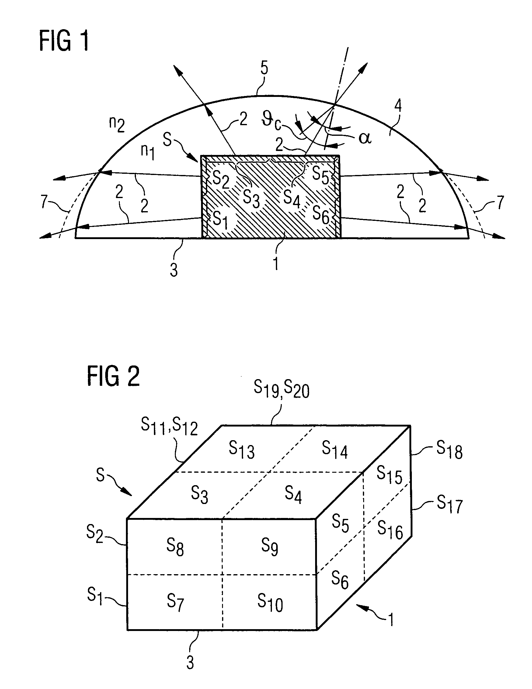
[0043]The lighting device depicted in FIG. 1, representing the first embodiment of the invention, comprises a light source 1 in the form of an LED chip that emits incoherent light with a total radiation power P. The radiation-emitting area S of light source 1 is divided into a plurality of subareas S1 to S20. Of these subareas, only subareas S1 to S6 are illustrated in FIG. 1, owing to the sectional view.

[0044]FIG. 2 shows a corresponding light source 1 in the form of an LED chip in perspective representation. The bottom face 3 serves as the mounting face of the LED chip and thus is not a radiation-emitting face. The other five side faces of the approximately cuboid light source make up the radiation-emitting area S of the light source. Each of these side faces is divided into four subareas, so radiation-emitting area S is therefore divided into a total of 20 subareas S1 to S20.

[0045]It should be noted that any other subdivision can also be carried out within the context of the inve...


PUM


Abstract

The invention relates to a lighting device comprising a light source (1) that emits incoherent light with a total radiation power P and has a radiation-emitting area (S) divided into a plurality of subareas (Si), wherein assigned to each subarea (Si) is a light ray (2) having a radiation power Pi and the sum of the radiation powers Pi is equal to the total radiation power P, and disposed after said light source (1) is an optical element (4) having a decoupling surface (5) and a total reflection angle (θc) assigned to said decoupling surface (5), said decoupling surface (5) being shaped so that at least for a portion of said light rays (2) the angle (α) of incidence on said decoupling surface (5) is smaller than the total reflection angle (θc), and the radiation power of said light rays collectively is greater than a predetermined fraction, equal to at least 50%, of the total radiation power P.

Description

FIELD OF THE INVENTION[0001]The present invention relates to a lighting device with an optimized decoupling surface.BACKGROUND OF THE INVENTION[0002]Such lighting devices include a light source and, disposed thereafter, an optical element having a decoupling surface for the light emitted by the light source. For example, the light source can be a semiconductor chip, with a suitably shaped potting compound as the optical element.[0003]For the light emitted by the light source to be decoupled as effectively as possible, the optical element must be adapted to the light source.[0004]With special light sources, particularly coherent light sources such as semiconductor lasers, for example, which have a comparatively well-defined and highly directed radiation characteristic, it is often possible to use prefabricated optical elements / element shapes that have been optimized for this class of light sources, such as lenses for parallelizing or focusing the light.[0005]Incoherent light sources,...

Claims


Application Information

Patent Timeline
IPC IPC(8): H01L33/54F21K99/00F21V5/04F21V7/04F21Y101/02G02B27/09H01L33/60
CPCG02B27/0955H01L33/54G02B19/0014G02B19/0061H01L33/60H01L2924/0002H01L2924/00
Inventor BLUMEL, SIMON
Owner OSRAM OPTO SEMICONDUCTORS GMBH
Why Eureka
Try Eureka