
Test system and test method for testing grating diffraction efficiency

A grating diffraction and efficiency testing technology, applied in the field of grating diffraction efficiency testing systems, can solve the problems of inability to meet application requirements in the field of high-power lasers and spectral analysis, inability to accurately control and accurately test, and achieve adjustable polarization direction and easy operation. , the effect of meeting application requirements

Inactive Publication Date: 2018-07-27
THE GENERAL DESIGNING INST OF HUBEI SPACE TECH ACAD
View PDF4 Cites 12 Cited by
  • Summary
  • Abstract
  • Description
  • Claims
  • Application Information

AI Technical Summary

Problems solved by technology

[0003] The current high-precision test method for diffraction efficiency cannot accurately control the incident fine wavelength and incident polarization, nor can it accurately test the diffraction efficiency (the ratio of diffracted light energy to incident light energy, which is related to wavelength), and cannot meet the requirements in the field of high-power laser and spectral analysis. Application requirements

Method used


Image

  • Test system and test method for testing grating diffraction efficiency
  • Test system and test method for testing grating diffraction efficiency
  • Test system and test method for testing grating diffraction efficiency

Examples


Embodiment Construction

[0024] In order to make the object, technical solution and advantages of the present invention more clear, the specific implementation manners of the present invention will be further described below in conjunction with the accompanying drawings and embodiments. It should be understood that the specific embodiments described here are only used to help the understanding of the present invention, and are not intended to limit the present invention. In addition, the technical features involved in the various embodiments of the present invention described below can be combined with each other as long as they do not constitute a conflict with each other.

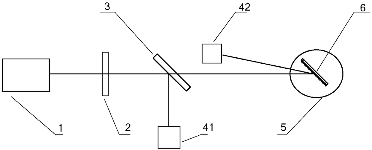
[0025] Such as figure 1 As shown, a grating diffraction efficiency test system includes a wavelength tunable laser placed on the optical axis along the optical path, a polarization control element, a spectroscopic device and a rotatable diffraction element, and two optical energy detectors, of which One cooperates with the spect...


PUM

PropertyMeasurementUnit
Wavelengthaaaaaaaaaa

Abstract

The invention discloses a test system for testing the grating diffraction efficiency. The system comprises a wavelength tunable laser device, a polarization control element, a light splitting device and a rotatable diffractive element. The wavelength tunable laser device, the polarization control element, the light splitting device and the rotatable diffractive element are arranged on an optical axis of an optical path in sequence. The system further comprises two light energy detectors. One of the two light energy detectors is matched with the light splitting device to enable a reference light beam to be separated from the light splitting device to directly enter the first light energy detector, while the other one of the two light energy detectors is matched with the diffractive elementto enable a test light beam split from the light splitting device to shoot into the diffractive element and then enter the second light energy detector after being diffracted by the diffractive element. The test system is high in laser wavelength precision, wide in line width and adjustable in polarization direction. By means of the test system, the spectrum, the angle and the polarization characteristics of the grating high-precision diffraction efficiency can be obtained. The test system is simple in configuration, convenient in operation and strong in environment adaptability. The application requirements in the field of high-power laser and spectral analysis can be met. The test system can be applied to the fields of spectral synthesis and spectral analysis.

Description

technical field [0001] The invention relates to the optical measurement field of grating diffraction efficiency test, in particular to a grating diffraction efficiency test system and method. Background technique [0002] Spectrum synthesis technology uses synthesis devices such as gratings (diffraction elements) to synthesize multiple narrow-linewidth semiconductors, optical fibers or solid-state lasers into a single high-power, high-brightness laser output. Spectral synthesis technology is an effective means to improve the power and energy while ensuring the quality of the beam. The grating (diffraction element) is a key component of spectrum synthesis. Its diffraction efficiency for different wavelengths determines the final synthesis effect. With the increase in the number of synthesis channels increase, higher requirements are placed on the accuracy of the diffraction efficiency test for precise wavelengths. On the other hand, in the field of scientific research spectr...

Claims


Application Information

Patent Timeline
IPC IPC(8): G01M11/02
CPCG01M11/00
Inventor 武春风李强姜永亮赵朋飞吕亮刘厚康丁舒林宋祥唐仕旺戴玉芬
Owner THE GENERAL DESIGNING INST OF HUBEI SPACE TECH ACAD
Learn More