Hologram recording method and hologram recording material

Inactive Publication Date: 2005-03-17
FUJIFILM CORP +1
24 Cites 35 Cited by

AI-Extracted Technical Summary

Problems solved by technology

However, the surface-relief phase hologram can hardly achieve full color formation, white color reproduction, high resolution and high diffraction efficiency and in recent years, a volume phase hologram capable of realizing these is attracting attention.
However, these known materials for recording a volume phase hologram are failing in satisfying all requirements required particularly in use for a high-sensitivity high-resolution full-color three-dimensional display, and improvements are demanded.
More specifically, for example, the gelatin bichromate system has high diffraction efficiency and low noise property but despite such advantages, this system has a problem in that the storability is very bad, a wet processing is necessary and the sensitivity is low.
The bleached silver halide system has high sensitivity but despite such an advantage, this system has a problem in that a wet processing is necessary, the bleaching process is cumbersome and the light fastness is poor.
The photorefractive material is rewritable but despite such an advantage, this material has a problem in that a high electric field must be applied at the recording and the recording preservability is bad.
The photochromic polymer system as represented by an azobenzene polymer material and the like is rewritable but despite such an advantage, this system has a problem in that the sensitivity is very low and the recording preservability is bad.
However, this system has a problem in that the sensitivity is about {fraction (1/1,000)} as compared with the bleached silver halide system, a heat-fixing processing as long as nearly 2 hours is necessary for enhancing the diffraction efficiency and because of radical polymerization, the diffraction wavelength and angle at the reproduction are changed due to the effect of polymerization inhibition by oxygen or resulting from shrinkage of the recording material after exposure and fixing.
However, in view of physical principle, existing two-dimensional optical mediums such as DVD-R can have a capacity of about 25 GB at most even if the recording/reproducing wavelength is shifted to a short wavelength, and a recording capacity large enough to cope with the requirement in future cannot be expected.
Among these, (1) high sensitivity is a property chemically conflicting with (3) high diffraction efficiency, (4) dry processing, (6) small shrinkage percentage after recording and (7) good preservability, and it is very difficult to attain high sensitivity at the same time with other properties.
For example, the bleached silver halide system has high sensitivity but since a wet processing is necessary, this system is generally not suitable for use in a high-density recording material.
WO97/44365A1 (Patent Document 4) discloses a rewritable hologram recording material using refractive index anisotropy and orientation control of an azobe...

Method used

Also, in order to form a large refractive index modulation, it is preferred that the polymerizable compound is easily movable in the hologram recording material.
As seen from Table 2, in the hologram recording material of the present invention, the light intensity of irradiation in the first step can be as small as ⅕ to {fraction (1/7)} as compared with the case of not using the second step. Since batch exposure can be performed in the second step, the recorded refractive index modulation can be amplified in the second step resulting from polymerization using the colored material which forms a latent image in the first step and therefore, the first step can be shortened, namely, high sensitivity can be achieved. Needless to say, high sensitivity by virtue of such amplification cannot be achieved in known materials.
At this time, in order to cause energy transfer with good efficiency, the excitation energy of the sensitizing dye or the colored material is preferably larger than the excitation energy of the dye precursor.
Furthermore, a protective layer for blocking oxygen may be formed on the hologram recording material. The protective layer may be formed by laminating a plastic-made film or plate such as polyolefin (e.g., polypropylene, polyethylene), polyvinyl chloride, polyvinylidene chloride, polyvinyl alcohol, polyethylene terephthalate and cellophane film, with use of electrostatic adhesion or an extruder, or by coating a solution of such a polymer. Also, a glass plate may be laminated. Between the protective layer and the photosensitive film and/or between the substrate and the photosensitive film, a pressure-sensitive adhesive or a liquid substance may be allowed to be present so as to increase the air tightness.
Furthermore, as compared with the recording method disclosed in Patent Document 4 where the change in orientation of a compound having birefringence such as azobenzene polymer is utilized, in the system of the present invention, the quantum yield is high to ensure high sensitivity and in addition, since the sensitizing dye is decomposed at the time of hologram recording or fixing by heat or light after recording or in the first or second step, to enable nondestructive reproduction, excellent preservability is also attained.
Furthermore, in order to give a large refractive index modulation, the dye precursor preferably becomes, after holographic exposure, a colored material having no absorption at a wavelength of a hologram reproducing light and having an absorption maximum in a region between a wavelength of a hologram reproducing light and a wavelength 200 nm shorter than the wavelength of the hologram reproducing light, more preferably a colored material having an absorption maximum in a region between a wavelength of a hologram reproducing light and a wavelength 100 nm shorter than the wavelength of the hologram reproducing light.
In order to form a large refractive index modulation, the difference in a refractive index between the polymerizable compound and the binder is preferably large in bulk and the difference in a refractive index is preferably 0.01 or more, more preferably 0.05 or more, still more preferably 0.1 or more.
In order to use the hologram recording material of the present invention as an optical recording medium in a holographic memory, a spatial light modulation element (SLM) such as DMD and LCD is preferably used to record a large number of two-dimensional digital data (referred to as “signal light”) . The recording is preferably carried out by multi-recording to enhance the recording density. Examples of multi-recording method employable herein include angle-multiple recording, phase-multiple recording, wavelength-multiple recording, and shift-multiple recording. Preferred among these multi-recording methods are angle-multiple recording and shift-multiple recording. In order to read the two-dimensional data reproduced, CCD or DMOS is preferably used.
In practice, the hologram recording material of the present invention was subjected to a multiplex hologram recording, by a multiplex recording of 10 times in a same position with an exposure amount each equal to {fraction (1/10)} of the exposure amount in the first step and with a reference light angle changed by 2° for each exposure (first step), followed by a flush irradiation with a light of a wavelength range of 370 to 410 nm (second step). And it was confirmed that each object light co...

Benefits of technology

According to the hologram recording material or the hologram recording method of the present invention in a system comprising a color-formation as a latent image by holographic exposure and a photo polymerization upon irradiation with a light having a different wavelength, the hologram recording can be performed with high sensitivity, high diffraction efficiency an...

Abstract

To provide a hologram recording method capable of satisfying high sensitivity and at the same time, satisfying high diffraction efficiency, good preservability, low shrinkage percentage, dry processing and multiplex recording properties, a hologram recording method comprises a first step of producing a latent image upon holographic exposure, and a second step of causing a polymerization reaction due to the latent image, to form a interference fringe providing a refractive index modulation, wherein the first and second steps are dry process; particularly, the first step is a step of producing a colored material to form the latent image and the second step is a step of causing the polymerization reaction upon irradiating the colored material with a light having a wavelength different from that of the holographic exposure, to form the interference fringe providing the refractive index modulation.

Application Domain

Technology Topic

Refractive index modulationPhotochemistry +6

Image

  • Hologram recording method and hologram recording material
  • Hologram recording method and hologram recording material
  • Hologram recording method and hologram recording material

Examples

  • Experimental program(1)

Example

EXAMPLE 1
Under red light, a sensitizing dye, an electron-donating compound, dye precursor group+a polymerization initiator, a polymerizable compound and a binder shown in Table 1 were dissolved in a methylene chloride of 2 to 5 times amount (acetone, acetonitrile or methanol being also employed if necessary) to prepare Hologram Recording Materials 101 to 106. Percentages are shown in wt. %. TABLE 1 Sensitizing Electron-donating Dye Precursor Group Polymerizable Sample Dye Compound Polymerization Initiator Compound Binder 101 D-118 (0.8%) ED-1 (10%) R-3 (5%) + I-104 (20%) M-1 (32.2%) Polydimethyl- siloxane (32%) 102 D-117 (0.4%) ED-1 (10%) R-3 (5%) + I-104 (20%) POEA:NVC = 2:1 polyvinyl acetal (32.6%) (32%) 103 D-115 (0.2%) ED-1 (10%) PB-3 (20%) + DD-47 (5%) M-2 (32.8%) poly(methylphenyl)- siloxane (32%) 104 D-118 (0.8%) ED-1 (10%) ES-1 (10%) + O—Cl-HABI (3%) POEA:NA = 4:1 cellulose (36.2%) acetate butyrate (40%) 105 D-117 (0.4%) ED-1 (10%) E-12 (20%) + POEA:NVC = 2:1 polymethyl O—Cl-HABI (1.8%) + MBO (1.2%) (30.6%) methacrylate (36%) 106 D-118 (0.8%) ED-1 (10%) E-25 (20%) + PB-3 (3%) EP-101 EO-1 (33%) (33.2%)
Hologram Recording Materials 101 to 106 each was blade coated on a glass substrate (superposed coating if necessary) to a thickness of about 80 μm to form a photosensitive layer and then, dried under heat at 40° C. for 3 minutes to remove the solvent by distillation. On the photosensitive layer, a cellulose triacetate (TAC) film was covered to complete Hologram Recording Materials 101 to 106.
Also as a comparative example, there was prepared a hologram recording material of radical polymerization photopolymer type, described in Example 1 of JP-A-6-43634.
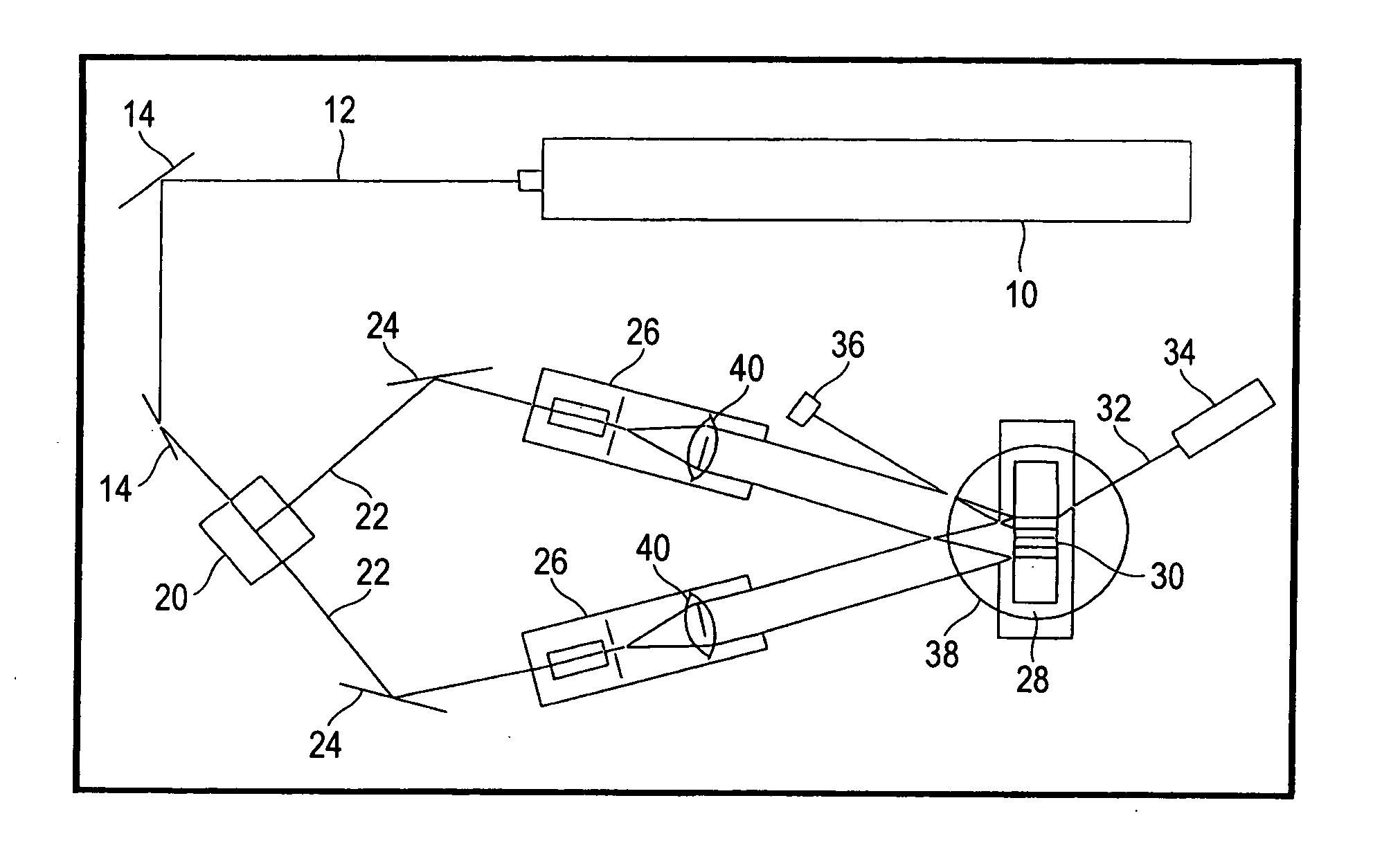
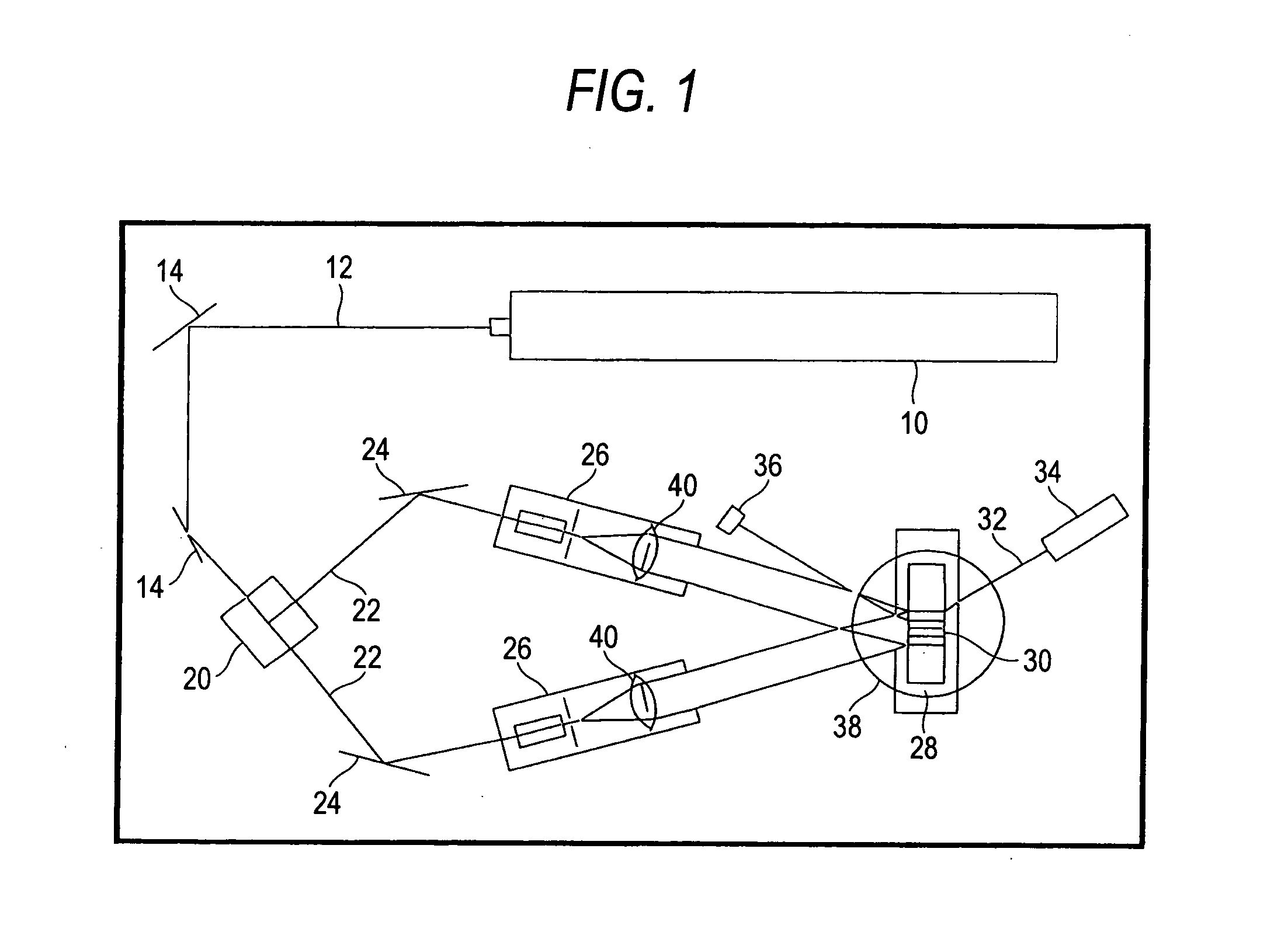
Each hologram recording material was subjected to recording by exposure with a two-beam optical system for the transmission hologram recording shown in FIG. 1 while using a YAG laser double wave (532 nm, output: 2 W) as the light source. The angle made by the object light and the reference light was 30°. The beam had a diameter of 0.6 cm and an intensity of 8 mW/cm2 and the exposure was performed by varying the holography exposure time in the range from 0.1 to 40 seconds (as an irradiation energy, from 0.8 to 320 mJ/cm2) . By passing a beam of He—Ne laser at 632 nm to the center of exposure region at a Bragg angle (first step), the ratio of the diffracted light to the incident light (diffraction efficiency) was measured in actual time. Also, a light in the wavelength region from 370 to 410 nm was irradiated on the entire surface of each hologram recording material (second step) and the diffraction efficiency was measured.
The diffraction efficiency after holographic exposure of the first step, the maximum diffraction efficiency and the shrink rate (a ratio of film thickness before and after the recording) after light irradiation of the second step, determined as above for each of Hologram Recording Materials 101 to 106, are shown in Table 2. TABLE 2 Diffraction Maximum Diffraction Efficiency after Efficiency after Amplification Sample First Step, η Second Step, η Factor* 101 15% 71% 6.3 102 14% 74% 6.7 103 13% 70% 6.1 104 14% 71% 6.6 105 13% 70% 5.7 106 14% 71% 5.6
*A value obtained by dividing an irradiation light intensity necessary for giving a maximum diffraction efficiency only by the first step without using the second step by an irradiation light intensity necessary for the first step when the second step is used.
As seen from Table 2, in the hologram recording material of the present invention, the light intensity of irradiation in the first step can be as small as ⅕ to {fraction (1/7)} as compared with the case of not using the second step. Since batch exposure can be performed in the second step, the recorded refractive index modulation can be amplified in the second step resulting from polymerization using the colored material which forms a latent image in the first step and therefore, the first step can be shortened, namely, high sensitivity can be achieved. Needless to say, high sensitivity by virtue of such amplification cannot be achieved in known materials.
It is also seen that in the hologram recording material of the present invention, Δn (calculated based on the Kogelnik's equation from the refractive index modulation amount, diffraction efficiency and film thickness) linearly increases according to the exposure amount (mJ/cm2) both after the first step and after the second step, which is advantageous for multiplex recording.
In practice, the hologram recording material of the present invention was subjected to a multiplex hologram recording, by a multiplex recording of 10 times in a same position with an exposure amount each equal to {fraction (1/10)} of the exposure amount in the first step and with a reference light angle changed by 2° for each exposure (first step), followed by a flush irradiation with a light of a wavelength range of 370 to 410 nm (second step). And it was confirmed that each object light could be reproduced by a reproducing light irradiation changed by 2° for each time. Thus the hologram recording material of the present invention is capable of multiplex recording with a same exposure amount, thus being suitable for multiplex recording. Stated differently, the hologram recording material of the present invention is capable of multiplex recording, thus achieving a recording of a high density (capacity).
On the other hand, in the hologram recording materials of JP-A-6-43634 and other known photopolymer methods, the polymerization of photopolymer progresses to retard the monomer displacement required for recording, in a latter period of the multiplex recording, thus requiring a larger exposure amount for a same recording in comparison with an early period of the multiplex recording, and constituting a difficulty in increasing the level of multiplicity or the recording density.
In the hologram recording method of the present invention, since the hologram recording (in the first step) is performed by using color formation as a latent image instead of polymerization, the above problem does not happen and the hologram recording method of the present invention is superior to other known photopolymer method.
The same effects were obtained even when in Hologram Recording Materials (Samples) 101 to 106, the sensitizing dye was changed to D-1, D-8, D-17, D-22, D-31, D-33, D-34, D-46, D-49, D-50, D-55, D-74, D-87, D-91, D-93, D-94, D-95, D-97, D-100, D-101, D-107, D-116, D-117, D-119, D-120, D-121 or D-122, even when in Samples 101 and 102, the acid generator (serving also as the cationic or radical polymerization initiator) was changed to 2-(4′-methoxyphenyl)-4,6-bis(trichloromethyl)-1,3,5-triazine, 4-diethylaminophenyldiazonium tetrafluoroborate, di(tert-butylphenyl)iodonium tetra(pentafluorophenyl)borate, tris-(4-methylphenyl)sulfonium tetra(pentafluorophenyl)borate, triphenylsulfonium methanesulfonate, triphenylsulfonium perfluoropentanoate, bis(1-(4-diphenylsulfonium)phenylsulfide ditriflate, benzoin tosylate, 2,6-dinitrobenzyl tosylate, N-tosylphthalic acid imide, I-101, I-102 or I-102 and even when in Samples 101 and 102, the acid-induced color forming dye precursor of the dye precursor group was changed to R-1, R-2, R-4, R-6 or R-7.
Also, the same effects were obtained even when in Samples 103 and 106, the base generator (serving also as the anionic polymerization initiator) of the dye precursor group was changed to PB-4, PB-8, PB-10, PB-12, PB-13, PB-19, PB-22, PB-32, PB-33 or PB-52, and even when in Sample 103, the base-induced color forming dye precursor (non-dissociated form of dissociation-type dye) was changed to DD-1, DD-4, DD-7, DD-10, DD-16, DD-23, DD-25, DD-35, DD-39, DD-44, D-47, D-48 or D-49.
Furthermore, the same effects were obtained even when in Samples 104 and 105, the radical polymerization initiator was changed to Irgacure 651, I-2, I-4, I-12, I-18, I-19, I-22, I-32, CDM-HABI, TCTM-HABI, tetrabutylammonium n-butyltriphenylborate or the like.
In addition, the same effects were obtained even when in Samples 105 and 106, the dye precursor was changed to E-4, E-5, E-13, E-15, E-16, E-18, E-24, E-25, E-28, E-29, E-32, E-33 E-37, E-38, E-42 or E-44.
In these, the light used for performing the entire surface exposure was at an optimal wavelength for each system.
The present application claims foreign priority based on Japanese Patent Application No. JP2003-300057, filed Aug. 25 of 2003, the contents of which is incorporated herein by reference.

PUM

no PUM

Description & Claims & Application Information

We can also present the details of the Description, Claims and Application information to help users get a comprehensive understanding of the technical details of the patent, such as background art, summary of invention, brief description of drawings, description of embodiments, and other original content. On the other hand, users can also determine the specific scope of protection of the technology through the list of claims; as well as understand the changes in the life cycle of the technology with the presentation of the patent timeline. Login to view more.

Similar technology patents

Integrated microfluidic optical device for sub-micro liter liquid sample microspectroscopy

InactiveUS20090051901A1Great sensitivityHigh sensitivityRadiation pyrometrySpectrum investigationSpectroscopySpectroscopic detection
Owner:DYNAMIC THROUGHPUT

Classification and recommendation of technical efficacy words

  • High sensitivity
  • High efficiency

System and method for optical coherence imaging

ActiveUS20060055936A1Sufficient signal to noise ratioHigh sensitivityInterferometersScattering properties measurementsPhysicsCoherent imaging
Owner:THE GENERAL HOSPITAL CORP

Catheter-free implantable needle biosensor

ActiveUS20080033269A1High sensitivitySimple stepSurgeryVaccination/ovulation diagnosticsNeedle electrodeElectricity
Owner:VIRTUE MEDICAL TECH (HUZHOU) CO LTD
Why Eureka
Try Eureka