
Method for manufacturing triangular groove echelon gratings with 90-degree vertex angles
A technology of triangular grooves and echelle gratings is applied to diffraction gratings, microlithography exposure equipment, photolithography exposure devices, etc., which can solve the problems of limiting the diffraction efficiency of gratings, and achieve improved diffraction efficiency, high diffraction efficiency, and short production cycle. Effect
- Summary
- Abstract
- Description
- Claims
- Application Information
AI Technical Summary
Problems solved by technology
Method used
Image

Examples
Embodiment 1
[0070] Example 1—Using an obliquely cut single crystal silicon wafer to make an echelle grating with a blaze angle of 54.7°:
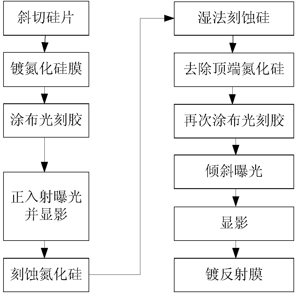
[0071] Echelle grating preparation method comprises the following steps, see figure 2 ;
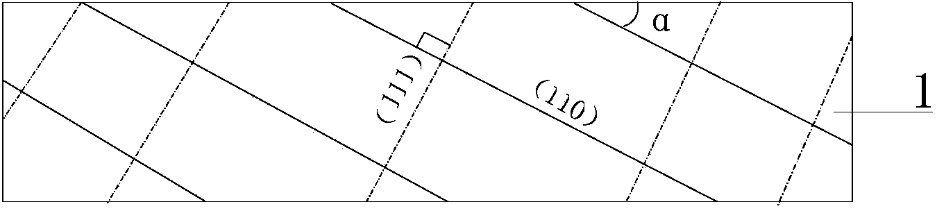
[0072] Select the obliquely cut single crystal silicon wafer 1, in order to manufacture an echelle grating with a blaze angle of 54.7°, the off angle is the surface of the obliquely cut silicon wafer and the original surface of the single crystal silicon wafer, namely (110) The angle α between the lattice planes is equal to 35.3°, see image 3 ;
[0073] Silicon nitride (SiNx) film 2 with a thickness of 50nm is plated on a silicon wafer using low-pressure chemical vapor deposition (LPCVD), see Figure 4 ;
[0074] Use the spin coating method to coat the positive photoresist 3 with a thickness of 200nm on the silicon nitride film, see Figure 5 , the thickness of the photoresist is determined according to the thickness of silicon nitride, which needs to be...
Embodiment 2
[0084] Example 2—Using an obliquely cut single crystal silicon wafer to make an echelle grating with a blaze angle of 76°:
[0085] Select obliquely cut monocrystalline silicon wafer 1, and make a blaze angle of 76°. The off-cut angle is the surface of the obliquely cut silicon wafer and the original surface, that is, the angle α between the (110) lattice plane is equal to 14°, see image 3 ;
[0086] Silicon nitride (SiNx) film 2 with a thickness of 50nm is plated on a silicon wafer using low-pressure chemical vapor deposition (LPCVD), see Figure 4 ;
[0087] Use the spin coating method to coat a positive photoresist 3 with a thickness of 100 nm on the silicon nitride film, see Figure 5 , the thickness of the photoresist is determined according to the thickness of silicon nitride, which needs to be greater than the thickness of the silicon nitride film layer 2, choose 100-1000nm;
[0088] Use the mask plate to expose on the ultraviolet lithography machine, and obtain a...
Embodiment 3
[0097] Example 3—Using a single crystal silicon wafer to make an echelle grating with a blaze angle of 54.7°:
[0098] Select monocrystalline silicon wafer 1, because the angle α between the surface of the silicon wafer and the (111) plane is equal to 54.7°. The angle α between the lattice planes is equal to 0°, see Figure 16 ;
[0099] Silicon nitride (SiNx) film 2 with a thickness of 50nm is plated on a silicon wafer using low-pressure chemical vapor deposition (LPCVD), see Figure 4 ;
[0100] Use the spin coating method to coat a positive photoresist 3 with a thickness of 100 nm on the silicon nitride film, see Figure 5 , the thickness of the photoresist is determined according to the thickness of silicon nitride, which needs to be greater than the thickness of the silicon nitride film layer 2, choose 100-1000nm;
[0101] Use the mask plate to expose on the ultraviolet lithography machine, and obtain a photoresist relief pattern consistent with the pattern on the ...
PUM
| Property | Measurement | Unit |
|---|---|---|
| thickness | aaaaa | aaaaa |
| angle | aaaaa | aaaaa |
Abstract
Description
Claims
Application Information