Apodized grating double-exposure making system and method based on dynamic optical shield plate

A secondary exposure and optical shading technology, applied in optics, optical components, optical waveguide and light guide, etc., can solve problems such as poor repeatability, inability to strictly control the shape of the apodization function, and high coherence requirements for ultraviolet light sources

Pending Publication Date: 2018-05-18
MINZU UNIVERSITY OF CHINA
View PDF0 Cites 3 Cited by
  • Summary
  • Abstract
  • Description
  • Claims
  • Application Information

AI Technical Summary

Problems solved by technology

However, the apodization phase mask method requires precise design and preparation of the phase template, and different phase masks need to be customized for different occasions, which is expensive; the UV pulse coherent writing method requires high coherence of the UV light source. The shape of the apodization function cannot be strictly controlled, and the repeatability is not good; altho

Method used


Image

  • Apodized grating double-exposure making system and method based on dynamic optical shield plate
  • Apodized grating double-exposure making system and method based on dynamic optical shield plate
  • Apodized grating double-exposure making system and method based on dynamic optical shield plate

Examples


Embodiment 1

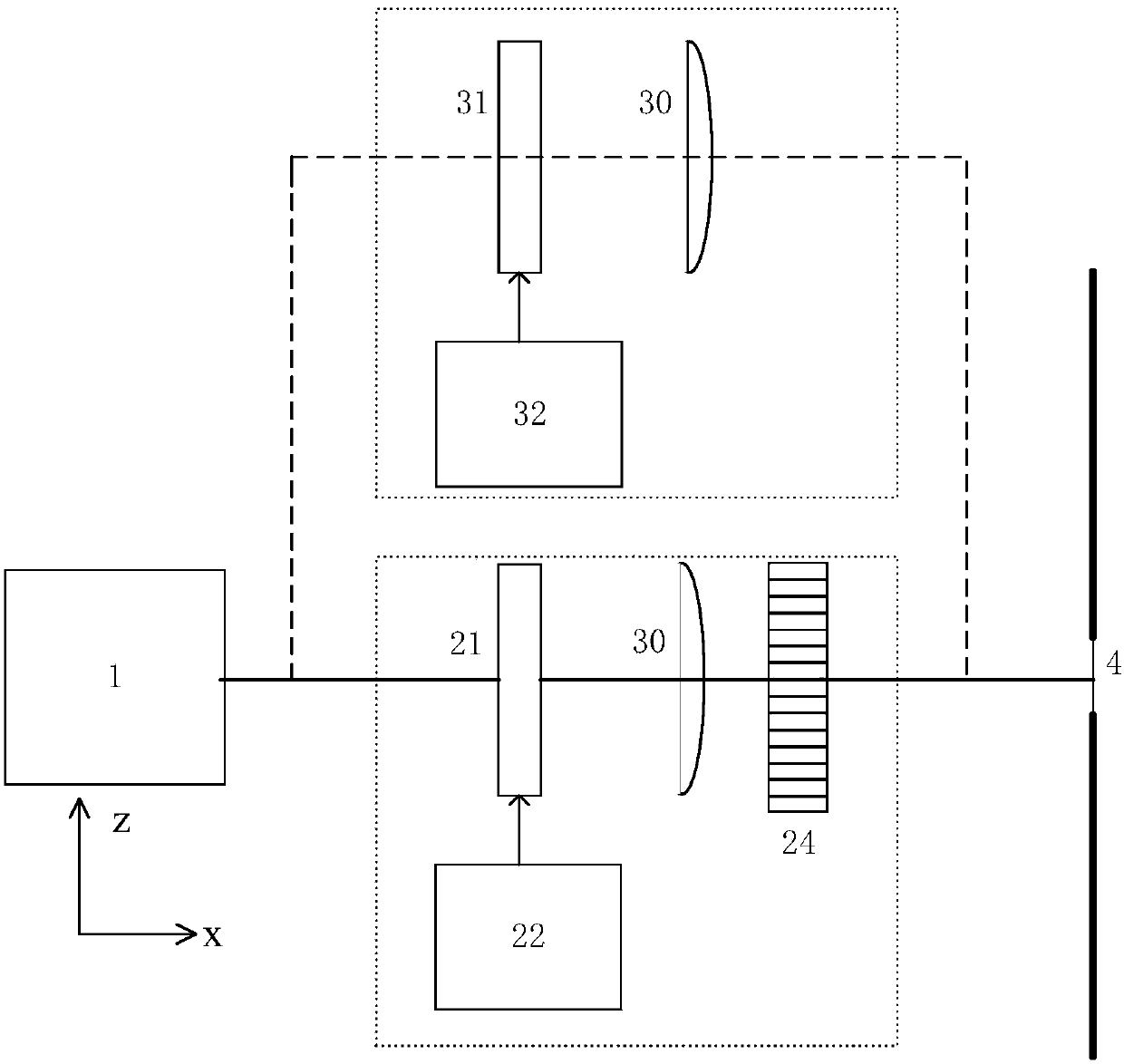
[0087] This embodiment adopts a distributed compensation method, such as Figure 4 As shown, between the ultraviolet excimer laser 1 and the optical path of the hydrogen-carrying fiber to be prepared, an optical shielding plate 21 for primary exposure, optical compensation plate for secondary exposure 31, plano-convex cylindrical mirror 30, uniform Phase mask 24 and uniform phase mask controller 52; the ultraviolet excimer laser emits ultraviolet light along the x-axis, which is shaped after a single exposure optical shielding plate, and the single-exposure optical shielding plate moves along the y-axis from the place where the light flux is minimum to At the place where the luminous flux is maximum, the controller of the one-time exposure optical shielding plate controls the movement displacement and speed of the one-time exposure optical shielding plate according to the motion function, so as to control the exposure length and exposure time of ultraviolet light in different are...

Embodiment 2

[0095] This embodiment adopts the simultaneous compensation method, such as Figure 5 As shown, the ultraviolet excimer laser emits ultraviolet light along the x-axis, which is divided into two beams by the beam splitter 7, and is placed one time along the x-axis between the first ultraviolet light and the optical path of the hydrogen-carrying fiber to be prepared The exposure optical shielding plate 21, the first plano-convex cylindrical mirror 23 and the uniform phase mask 24 are placed between the second ultraviolet light and the optical path of the hydrogen-carrying fiber to be prepared, and the second exposure optical compensation is sequentially placed along the x axis The plate 31 and the second plano-convex cylindrical lens 33; the first ultraviolet light is shaped by the one-time exposure optical shielding plate, and the one-time exposure optical shielding plate controller controls the movement displacement and speed of the one-time exposure optical shielding plate accor...


PUM


Abstract

The invention discloses an apodized grating double-exposure making system and method based on a dynamic optical shield plate. A single-exposure optical shield plate and a double-exposure optical compensation plate are adopted. Holes forming a conjugate function are respectively arranged in the centers of the two baffles. A single-exposure optical shield plate controller controls the speed of movement of the single-exposure optical shield plate along a direction perpendicular to a hydrogen-loaded fiber in order to control the time of exposure in different regions and complete single exposure. Adouble-exposure optical compensation plate controller controls the speed of movement of the double-exposure optical compensation plate to complete double-exposure compensation, so as to realize DC refractive index compensation for an apodized grating. The system and the method cost low. An optical baffle is used as a shield plate. The system has a simple structure. The precision is controllable.The movement of the optical shield plate is controlled digitally. The system and the method have the advantages of easy adjustment, flexible control, good repeatability, high efficiency and easy industrial production. A clear movement function is given, and any apodized grating can be made.

Description

Technical field [0001] The invention relates to an optical fiber sensing preparation technology, in particular to an apodized grating secondary exposure production system based on a dynamic optical shielding plate and a preparation method thereof. Background technique [0002] Fiber grating (FBG) is a type of optical fiber device whose refractive index changes periodically along the axial length of the fiber. It can be designed to produce unique filtering and dispersion characteristics through a special refractive index structure. It is used in fiber sensing, laser technology, and wavelength division multiplexing. And other fields have wide application value. The half-wave linewidth (FWHM) of the grating reflection spectrum, the side mode rejection ratio (SMSR) and the side mode roll-off characteristic (SLSR) determine the system wavelength multiplexing and test accuracy. By adopting appropriate apodization technology in the manufacturing process of fiber grating, the side lobes...

Claims


Application Information

Patent Timeline
IPC IPC(8): G02B6/02
CPCG02B6/02085G02B6/02123
Inventor 陈根祥田恺吕敏王义全
Owner MINZU UNIVERSITY OF CHINA
Why Eureka
Try Eureka