Lithographic apparatus, device manufacturing method, and device manufactured thereby

a technology of lithographic apparatus and manufacturing method, applied in the direction of printers, photo-taking processes, photographic processes, etc., can solve the problems of high thermal stress and cracking, unwanted exposure of resist, sublimation and oxidation in the high power level

Inactive Publication Date: 2004-01-13
ASML NETHERLANDS BV
View PDF4 Cites 33 Cited by
  • Summary
  • Abstract
  • Description
  • Claims
  • Application Information

AI Technical Summary

Benefits of technology

According to the present invention there is provided a lithographic projection apparatus including a radiation system to provide a projection beam of radiation, a support structure to support patterning structure, the patterning structure serving to pattern the projection beam according to a desired pattern, a substrate table for holding a substrate, a projection system to project the patterned beam onto a target portion of the substrate, and a grating spectral filter comprised in said radiation system for passing radiation of desired wavelengths to form said projection beam and for deflecting radiation of undesired wavelengths. Embodiments of the grating spectral filter of the present invention are more efficient, directing a higher proportion of the desired radiation into the projection beam, and more robust than membrane filters used in the prior art. In particular, certain embodiments of the grating spectral filter are less prone to thermal radiation because they can reflect rather than absorb the undesired radiation, because they can be made thicker and because cooling channels can be integrated or attached to a rear surface thereof. By suitable selection of parameters of the grating filter, such as the line density and angle of the incident beam, the resolving power, which determines the wavelength band passed into the projection beam, can be adjusted as desired. Further, a reflective, grazing incidence grating filter of the size necessitated by the beam diameter can be provided more easily than a transmisive filter.
The grating spectral filter is preferably a blazed grating because such gratings have a high diffraction efficiency. For maximum reflection efficiency, the grating is preferably used at grazing incidence. A laminar grating with a square wave surface profile may also be used and can be cheaply manufactured.

Problems solved by technology

These unwanted frequencies will propagate and cause heating problems in the illumination and projection systems and cause unwanted exposure of the resist if not blocked; although the multilayer mirrors of the illumination and projection systems are optimized for reflection of the desired wavelength, e.g. 13 nm, they are optically flat and have quite high reflectivities at IR, visible and UV wavelengths.
However, such a film is very delicate and becomes very hot, 200-300.degree. C. or more, leading to high thermal stresses and cracking, sublimation and oxidation in the high power levels necessary in a lithographic projection apparatus.

Method used


Image

  • Lithographic apparatus, device manufacturing method, and device manufactured thereby
  • Lithographic apparatus, device manufacturing method, and device manufactured thereby
  • Lithographic apparatus, device manufacturing method, and device manufactured thereby

Examples


embodiment 1

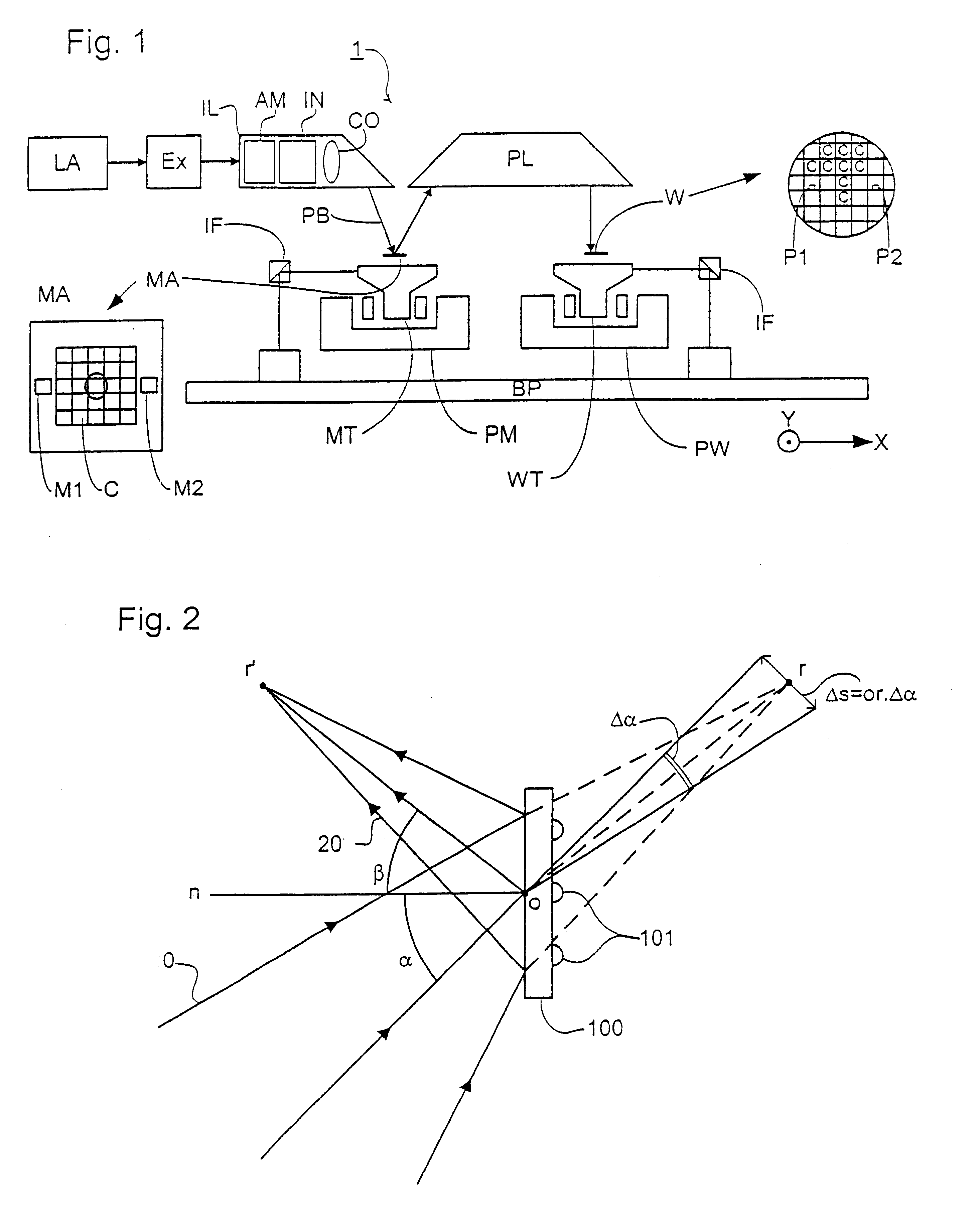
FIG. 1 schematically depicts a lithographic projection apparatus according to a particular embodiment of the invention. The apparatus includes:

a radiation system Ex, IL, for supplying a projection beam PB of radiation (e.g., EUV radiation), which in this particular case also comprises a radiation source LA;

a first object table (mask table) MT provided with a mask holder for holding a mask MA (e.g., a reticle), and connected to first positioning means PM for accurately positioning the mask with respect to item PL;

a second object table (substrate table) WT provided with a substrate holder for holding a substrate W (e.g., a resist-coated silicon wafer), and connected to second positioning means PW for accurately positioning the substrate with respect to item PL;

a projection system ("lens") PL (e.g., a mirror group) for imaging an irradiated portion of the mask MA onto a target portion C (e.g., comprising one or more dies) of the substrate W.

As here depicted, the apparatus is of a refle...

embodiment 2

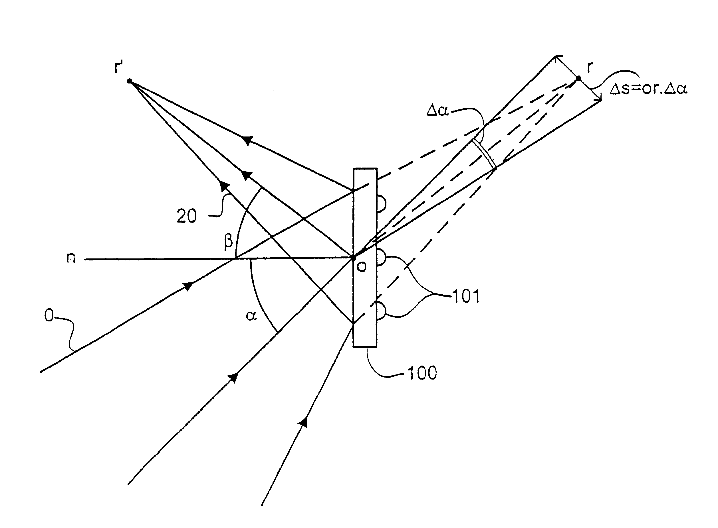
In a second embodiment of the invention, which may be the same as the first embodiment of the invention save as described below, the grating is positioned in a diverging beam so there is a real object and virtual image. Using a constant line spacing grating, the distances or and or', the distances from the grating to the object and image, are different. In both the first and second embodiments, a grating with a variable line spacing can be used to alter these distances and make them equal in which case the grating has almost the same properties as a plane mirror. The gratings of both the first and second embodiments can be combined with another reflector, e.g. a scatter plate or spherical focusing mirror, included in the illumination system to have a combined function.

embodiment 3

In a third embodiment of the invention, which may be the same as the first or second embodiments save as described below, a grating structure is applied to a grazing incidence mirror in the illumination system.

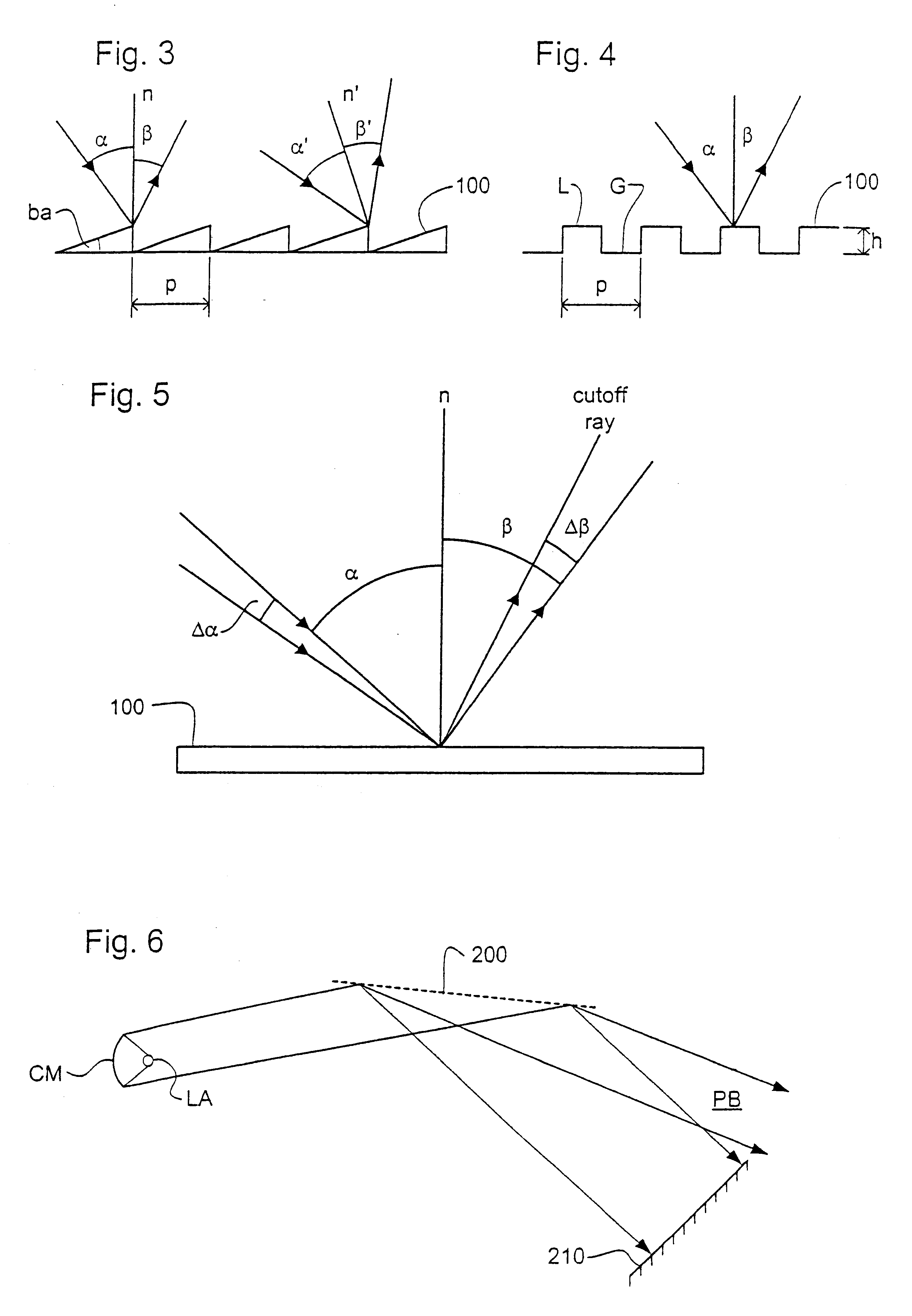
As shown in FIG. 6, radiation from radiation source LA is collected by collector mirror CM and directed towards grazing incidence reflector 200. The beam directed towards reflector 200 contains both the desired EUV radiation, e.g. at a wavelength of about 13.5 nm, and undesired radiation at higher wavelengths. If the source LA is, for example, a laser-produced xenon-plasma, there may be of the order of 10 times as much energy in the UV radiation band of 100-200 nm as in the desired EUV band around 13.5 nm.

To extract the unwanted longer-wavelength radiation, a diffraction grating structure, such as consisting of a phase grating as shown in FIG. 4, is applied to the reflector 200. The grating is arranged so that the optical path difference (OPD) between rays having been reflecte...


PUM

PropertyMeasurementUnit
blazing angleaaaaaaaaaa
wavelengthaaaaaaaaaa

Abstract

In a lithographic projection apparatus, a grating spectral filter is used to filter an EUV projection beam. The grating spectral filter is preferably a blazed, grazing incidence, reflective grating. Cooling channels may be provided in or on the rear of the grating spectral filter. The grating spectral filter may be formed of a material effectively invisible to the desired radiation.

Description

This application claims priority to European Patent Application 00308903.4, filed Oct. 10, 2000 which is herein incorporated by reference in its entirety.1. Field of the InventionThe present invention relates generally to a lithographic projection apparatus and more particularly to a lithographic projection apparatus including a spectral filter.2. Background of the Related ArtThe term "patterning structure" as here employed should be broadly interpreted as referring to structure that can be used to endow an incoming radiation beam with a patterned cross-section, corresponding to a pattern that is to be created in a target portion of the substrate; the term "light valve" can also be used in this context. Generally, the pattern will correspond to a particular functional layer in a device being created in the target portion, such as an integrated circuit or other device (see below). Examples of such patterning structure include:A mask. The concept of a mask is well known in lithography...

Claims


Application Information

Patent Timeline
Patent Type & Authority Patents(United States)
IPC IPC(8): G03F7/20G03F7/22H01L21/027G02B5/18
CPCG03F7/70191G03F7/702G03F7/70575G03F7/20
Inventor VAN ELP, JANLEENDERS, MARTINUS HENDRIKUS ANTONIUSBANINE, VADIM YEVGENYEVICHVISSER, HUGO MATTHIEUBAKKER, LEVINUS PIETER
Owner ASML NETHERLANDS BV
Why Eureka
Try Eureka