Image processing method and device and computer storage medium
A technology of image processing and convolution model, applied in the field of video analysis, can solve the problem that image processing technology cannot be realized through 2D convolution model
Pending Publication Date: 2020-07-03
ZHEJIANG DAHUA TECH
0 Cites 1 Cited by
AI-Extracted Technical Summary
Problems solved by technology
[0005] The technical problem mainly solved by this application is to provide an image processing method, which can solve the problem that ...
Abstract
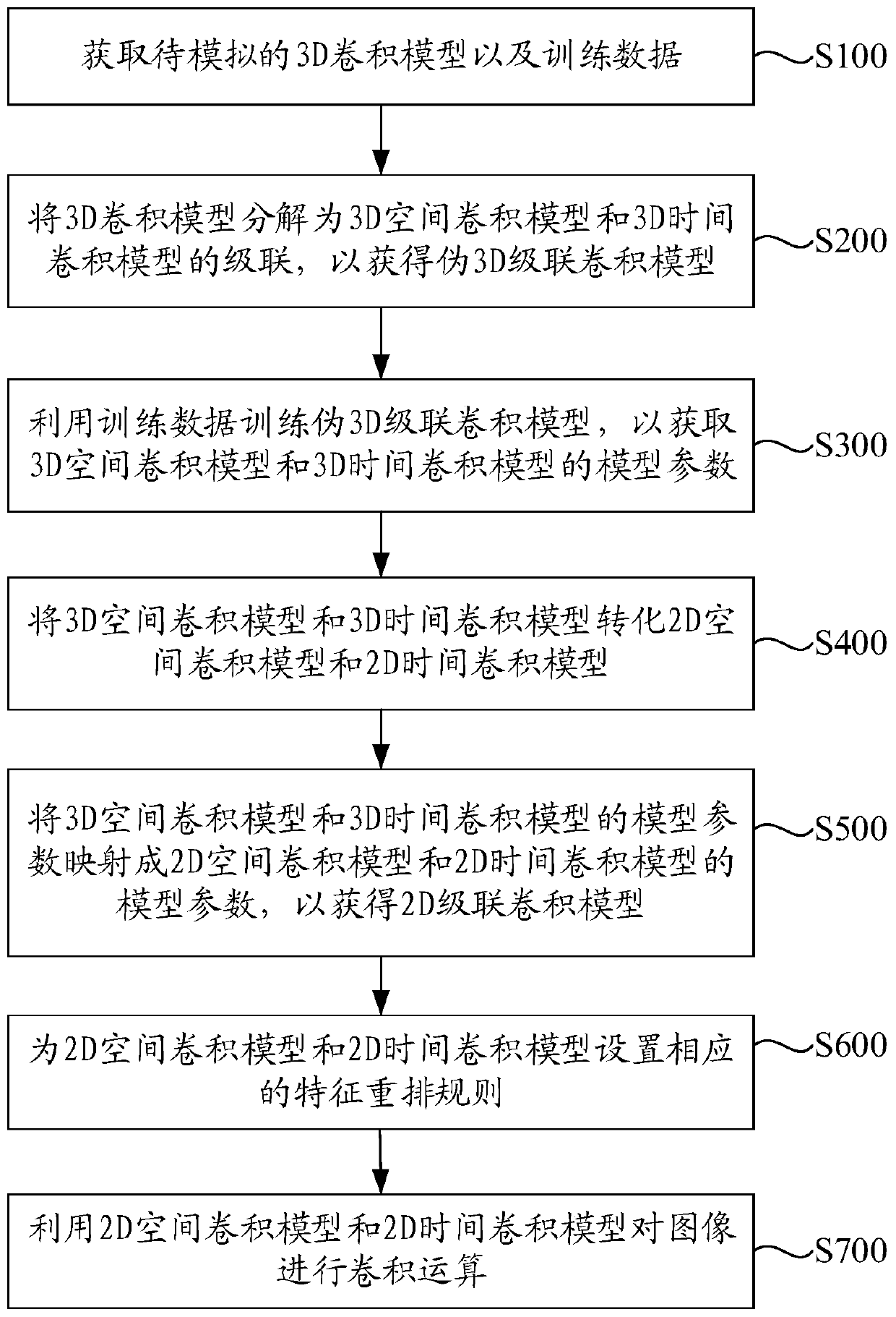
The invention discloses an image processing method and device and a storage medium. The method comprises the steps of obtaining a to-be-simulated 3D convolution model and training data; decomposing the 3D convolution model into cascading of a 3D space convolution model and a 3D time convolution model to obtain a pseudo 3D cascading convolution model; training a pseudo 3D cascade convolution modelby using the training data, and obtaining parameters of a 3D spatial convolution model and a 3D time convolution model; converting the 3D space convolution model and the 3D time convolution model intoa 2D space convolution model and a 2D time convolution model; setting a feature rearrangement rule for the 2D spatial convolution model and the 2D time convolution model; mapping model parameters ofthe 3D spatial convolution model and the 3D time convolution model into parameters of a 2D spatial convolution model and a 2D time convolution model to obtain a 2D cascaded convolution model; and performing convolution operation on the image by using the 2D spatial convolution model and the 2D time convolution model. By means of the mode, image processing conducted through 3D convolution operationcan be achieved through the 2D convolution model.
Application Domain
Character and pattern recognitionComplex mathematical operations
Technology Topic
ConvolutionAlgorithm +3
Image
Examples
- Experimental program(1)
Example Embodiment
[0013] The following will clearly and completely describe the technical solutions in the embodiments of the present application in conjunction with the drawings in the embodiments of the present application. Obviously, the described embodiments are only a part of the embodiments of the present application, rather than all the embodiments. Based on the embodiments in this application, all other embodiments obtained by those of ordinary skill in the art without creative work fall within the protection scope of this application.
[0014] The terms "first" and "second" in this application are only used for descriptive purposes, and cannot be understood as indicating or implying relative importance or implicitly indicating the number of technical features shown. Therefore, the features defined with "first" and "second" may explicitly or implicitly include at least one of the features. In addition, the terms "include" and "have" and any of their variations are intended to cover non-exclusive inclusion. For example, a process, method, system, product, or device that includes a series of steps or units is not limited to the listed steps or units, but optionally includes unlisted steps or units, or optionally also includes Other steps or units inherent in these processes, methods, products or equipment.
[0015] The reference to "embodiments" herein means that a specific feature, structure or characteristic described in conjunction with the embodiments may be included in at least one embodiment of the present application. The appearance of the phrase in various places in the specification does not necessarily refer to the same embodiment, nor is it an independent or alternative embodiment mutually exclusive with other embodiments. Those skilled in the art clearly and implicitly understand that the embodiments described herein can be combined with other embodiments.
[0016] Refer to figure 1 with figure 2 , figure 1 Is a schematic diagram of an embodiment of a general implementation method of a 3D convolution model, figure 2 It is a schematic diagram of an embodiment of a general implementation method of a 2D convolution model. figure 1 The convolution kernel of the 3D convolution model shown is k 1 ×k 2 ×k 3 , The input feature is F∈R B×C×T×H×W , After the convolution operation of the 3D convolution model, the output feature is F′∈R B×C′×T′×H′×W′. Among them, B represents the number of samples feature, C represents the channel feature, T represents the time feature, and H and W represent the height and width of the image or video frame, respectively. figure 2 The convolution kernel of the 2D convolution model shown is k 4 ×k 5 , The input feature is F∈R B×C×H×W , After the convolution operation of the 3D convolution model, the output feature is F′∈R B×C′×H′×W′.
[0017] This embodiment provides an image processing method, please refer to image 3 , image 3 This is a schematic flowchart of an embodiment of the image processing method of this application. The specific steps include:
[0018] S100: Obtain a 3D convolution model to be simulated and training data.
[0019] In this embodiment, figure 1 The 3D convolution model shown as an example, the size of the convolution kernel of the 3D convolution model to be simulated is k 1 ×k 2 ×k 3 , Where k 1 Is the time depth, k 2 Is the height dimension, k 3 Is the width dimension. In this step, in order to obtain better training results, in addition to obtaining training data, negative sample data must be obtained.
[0020] S200: Decompose the 3D convolution model into a cascade of a 3D spatial convolution model and a 3D temporal convolution model to obtain a pseudo 3D cascade convolution model.
[0021] The convolution kernel of the 3D spatial convolution model obtained by decomposition is 1×k 2 ×k 3 , The convolution kernel of the 3D temporal convolution model is k 1 ×1×1. In the pseudo 3D cascaded convolution model composed of a 3D spatial convolution model and a 3D temporal convolution model, the output feature of the 3D spatial convolution model is used as the input feature of the 3D temporal convolution model.
[0022] S300, using the training data to train the pseudo 3D cascaded convolution model to obtain model parameters of the 3D spatial convolution model and the 3D temporal convolution model.
[0023] S400, converting the 3D spatial convolution model and the 3D temporal convolution model into a 2D spatial convolution model and a 2D temporal convolution model.
[0024] In order to completely convert the 3D convolution model into a 2D convolution model, the 3D spatial convolution model needs to be converted into a 2D spatial convolution model. First, the 3D temporal convolution model needs to be converted into a 2D temporal convolution model. Among them, the 2D space The size of the convolution kernel of the convolution model is k 2 ×k 3 , The size of the convolution kernel of the 2D temporal convolution model is k 1 ×1.
[0025] S500: Map the model parameters of the 3D spatial convolution model and the 3D temporal convolution model to the model parameters of the 2D spatial convolution model and the 2D temporal convolution model to obtain a 2D cascaded convolution model.
[0026] In this step, the model parameters of the 3D spatial convolution model and the 3D temporal convolution model trained in step S300 are mapped to the 2D spatial convolution model and the 2D temporal convolution model as the model parameters of the 2D spatial convolution model And the parameters of the 2D temporal convolution model.
[0027] Specifically, the 2D spatial convolution model may be a grouped convolution model with GROUP=T, and its convolution kernel is k 2 ×k 3 , Where the model parameters of the 3D space convolution model need to be copied in T copies in the input channel dimension, and the time dimension is cancelled. For example, the model parameter of the 3D space convolution model is the dimension C×C′×1×k 2 ×k 3 The model parameters of the 3D space convolution model are copied to the input channel dimension C for T copies, and the third dimension is canceled to obtain the model parameters of the 2D space convolution model. The model parameters of the 2D space convolution model are of dimension TC×C′×k 2 ×k 3 Tensor. Among them, T is the time depth of the input feature corresponding to the 3D convolution model.
[0028] Refer to Figure 4 , Figure 4 This is a schematic diagram of an embodiment of the application of grouped convolution in the image processing method of this application. In the figure, (a) represents the input video or image information, and (c) represents the input video or image information with a time depth of T into T groups. Perform convolution operations. In this way, the input video or image with a time depth of T can be subjected to T groups of grouped convolution operations.
[0029] Optionally, the model parameters of the 3D time convolution model are directly reused as the model parameters of the 2D time convolution model.
[0030] S600: Set corresponding feature rearrangement rules for the 2D spatial convolution model and the 2D temporal convolution model.
[0031] The input features required by the 3D convolution model are five-dimensional input features, for example, figure 1 The five-dimensional input feature shown is F ∈ R B×C×T×H×W , After 3D convolution, the output feature is F′∈R B×C′×T′×H′×W′. The input features required by the 2D convolution model are four-dimensional input features. If the five-dimensional input features are directly input into the 2D convolution model, the computing power of the 2D convolution model will be exceeded, resulting in a situation that cannot be processed. Therefore, it needs to be 2D The spatial convolution model and the 2D temporal convolution model set corresponding feature rearrangement rules to rearrange the five-dimensional input features.
[0032] Specifically, the first feature rearrangement rule is set to exchange the channel dimension and time dimension of the input feature corresponding to the 3D convolution model, and merge the time dimension and channel dimension of the exchanged input feature to form a 2D Input characteristics of the spatial convolution model.
[0033] Input feature F∈R B×C×T×H×W The dimensional changes for dimensional rearrangement according to the above-mentioned first characteristic rearrangement rule are as follows:
[0034] B×C×T×H×W→B×T×C×H×W→B×TC×H×W,
[0035] After rearrangement, the dimension of the input feature of the 2D spatial convolution model is B×TC×H×W. After the convolution calculation of the 2D spatial convolution model, the dimension of the output feature of the 2D spatial convolution model is B×TC ′×H′×W′, the output feature obtained by the convolution calculation of the 2D spatial convolution model can be expressed as R B×TC′×H′×W′.
[0036] The 2D spatial convolution model mentioned above ignores temporal features. The extraction of temporal features needs to be achieved through the 2D temporal convolution model, while the convolution calculation of the 2D temporal convolution model needs to slide in the temporal dimension. Therefore, the 2D spatial convolution is required. Product model output characteristics R B×TC′×H′×W′ Perform feature rearrangement.
[0037] Specifically, the second feature rearrangement rule is set to split the combined time dimension and channel dimension of the output feature of the 2D spatial convolution model, and merge the height dimension and width dimension of the output feature of the 2D spatial convolution model , And exchange the time dimension and channel dimension after splitting the output feature of the 2D space convolution model to serve as the input feature of the 2D time convolution model. After the second feature rearrangement rule, the output feature R B×TC×H×W Rearrangement of dimensions.
[0038] The output feature R obtained by the convolution calculation of the 2D spatial convolution model B×TC′×H′ ×W ′ , The dimensional changes of the feature rearrangement according to the above second feature rearrangement rule are as follows:
[0039] B×TC′×H′×W′→B×T×C′×H′×W′→B×T×C′×H′W′→B×C′×T×H′W′.
[0040] After rearrangement, the dimension of the input feature of the 2D time convolution model is B×C′×T×H′W′. After the convolution calculation of the 2D time convolution model, the dimension of the output feature of the 2D time convolution model is obtained. Is B×C′×T′×H′W′, and the output feature obtained by the convolution calculation of the 2D time convolution model can be expressed as R B×C′×T′×H′W′.
[0041] Before the end of the convolution calculation, the output feature R obtained by the convolution calculation of the 2D temporal convolution model B×C′×T′×H′W′ Is not the final output result, output feature R B×C′×T′×H′W′ Need to return to the 2D spatial convolution model to continue the convolution calculation, so the output feature R obtained by the convolution calculation of the 2D temporal convolution model B×C′×T′×H′W′ Feature rearrangement is required.
[0042] Specifically, the third feature rearrangement rule is set to exchange the channel dimension and time dimension of the output feature of the 2D time convolution model, and split the combined height dimension and width dimension of the output feature of the 2D space convolution model , And combine the time dimension and the channel dimension after the output feature exchange of the 2D spatial convolution model to use as the output feature of the 2D cascaded convolution model.
[0043] The output feature R obtained by the convolution calculation of the 2D spatial convolution model B×C′×T′×H′W′ , The dimensional changes of the feature rearrangement according to the above third feature rearrangement rule are as follows:
[0044] B×C′×T′×H′W′→B×T′×C′×H′W′→B×T′×C′×H′×W′→B×T′C′×H′× W'.
[0045] The output feature R obtained by the convolution calculation of the 2D spatial convolution model B×C′×T′×H′W′ After the feature rearrangement of the third rearrangement rule, the dimension of the obtained feature is B×T′C′×H′×W′, and the obtained feature R B×T′C′×H′×W′ You can input the 2D spatial convolution model for convolution calculation.
[0046] S700, using the 2D spatial convolution model and the 2D temporal convolution model to perform a convolution operation on the image;
[0047] After the above steps S100-S600, the 3D convolution operation can be simulated by 2D convolution, and the convolution operation on multiple frames of images or videos can be realized to realize image classification, action recognition, etc.
[0048] See Figure 5 , Figure 5 It is a schematic block diagram of the circuit structure of an embodiment of the image processing apparatus of the present application. Such as Figure 5 As shown, the image processing device includes a processor 11 and a memory 12 coupled to each other. A computer program is stored in the memory 12, and the processor 11 is configured to execute the computer program to implement the steps of the above-mentioned embodiment of the image processing method of the present application.
[0049] For the description of each step of processing execution, please refer to the description of each step of the above-mentioned embodiment of the image processing method of the present application, which will not be repeated here.
[0050] In the embodiments of the present application, the disclosed image processing method and image processing device may be implemented in other ways. For example, the embodiments of the image processing apparatus described above are only illustrative. For example, the division of the modules or units is only a logical function division, and there may be other division methods in actual implementation, such as multiple Units or components can be combined or integrated into another system, or some features can be omitted or not implemented. In addition, the displayed or discussed mutual coupling or direct coupling or communication connection may be indirect coupling or communication connection through some interfaces, devices or units, and may be in electrical, mechanical or other forms.
[0051] The units described as separate components may or may not be physically separated, and the components displayed as units may or may not be physical units, that is, they may be located in one place, or they may be distributed on multiple network units. Some or all of the units may be selected according to actual needs to achieve the objectives of the solutions of this embodiment.
[0052] In addition, the functional units in the various embodiments of the present application may be integrated into one processing unit, or each unit may exist alone physically, or two or more units may be integrated into one unit. The above-mentioned integrated unit can be realized in the form of hardware or software functional unit.
[0053] If the integrated unit is implemented in the form of a software functional unit and sold or used as an independent product, it can be stored in a computer readable storage medium. Based on this understanding, the technical solution of this application essentially or the part that contributes to the existing technology or all or part of the technical solution can be embodied in the form of a software product, and the computer software product is stored in a storage medium , Including several instructions to enable a computer device (which may be a personal computer, a server, or a network device, etc.) or a processor to execute all or part of the steps of the methods described in the various embodiments of the present application. The aforementioned storage media include: U disk, mobile hard disk, read-only memory (ROM, Read-Only Memory), random access memory (RAM, Random Access Memory), magnetic disk or optical disk and other media that can store program code .
[0054] The above are only examples of this application, and do not limit the scope of this application. Any equivalent structure or equivalent process transformation made by using the description and drawings of this application, or directly or indirectly applied to other related technologies In the same way, all fields are included in the scope of patent protection of this application.
PUM


Description & Claims & Application Information
We can also present the details of the Description, Claims and Application information to help users get a comprehensive understanding of the technical details of the patent, such as background art, summary of invention, brief description of drawings, description of embodiments, and other original content. On the other hand, users can also determine the specific scope of protection of the technology through the list of claims; as well as understand the changes in the life cycle of the technology with the presentation of the patent timeline. Login to view more.