In-plane rotation invariant object detection in digitized images

a technology of in-plane rotation and object detection, applied in the field of digital image processing, can solve the problems of inability to deal with only a limited range of object poses or viewpoints, inability to conclude, and failure to achieve overall tasks

Inactive Publication Date: 2007-09-25
MONUMENT PEAK VENTURES LLC
View PDF0 Cites 154 Cited by
  • Summary
  • Abstract
  • Description
  • Claims
  • Application Information

AI Technical Summary

Benefits of technology

[0018]It is an advantageous effect of the invention that improved methods, computer systems, and computer program products are provided, in which the most likely in-plane orientation of objects can be rapidly estimated and in which substantial out-of-plane rotation is tolerated.
that improved methods, computer systems, and computer program products are provided, in which the most likely in-plane orientation of objects can be rapidly estimated and in which substantial out-of-plane rotation is tolerated.

Problems solved by technology

One common weakness of such detectors is a capability to deal with only a limited range of object poses or viewpoints.
But this conclusion is not true.
Depending on the speed requirements of that processing, it may be true that insufficient speed in the face detection portion of the processing would render the overall tasks unsuccessful.
These approaches tend to have the disadvantage of a large false positive rate, particularly when out-of-plane rotation is present.
A further problem of many of the above approaches is dependence upon correction orthogonal orientation of images prior to object location.
Possible ameliorative measures, such as multiple passes, additional training, and use of multiple classifiers add complexity and require additional time.
The approaches of these publications have the shortcoming of a risk that the time cost of the rotation estimation would approach that of the face classification decision, leading to a substantial speed loss in the overall detection system.

Method used


Image

  • In-plane rotation invariant object detection in digitized images
  • In-plane rotation invariant object detection in digitized images
  • In-plane rotation invariant object detection in digitized images

Examples


Embodiment Construction

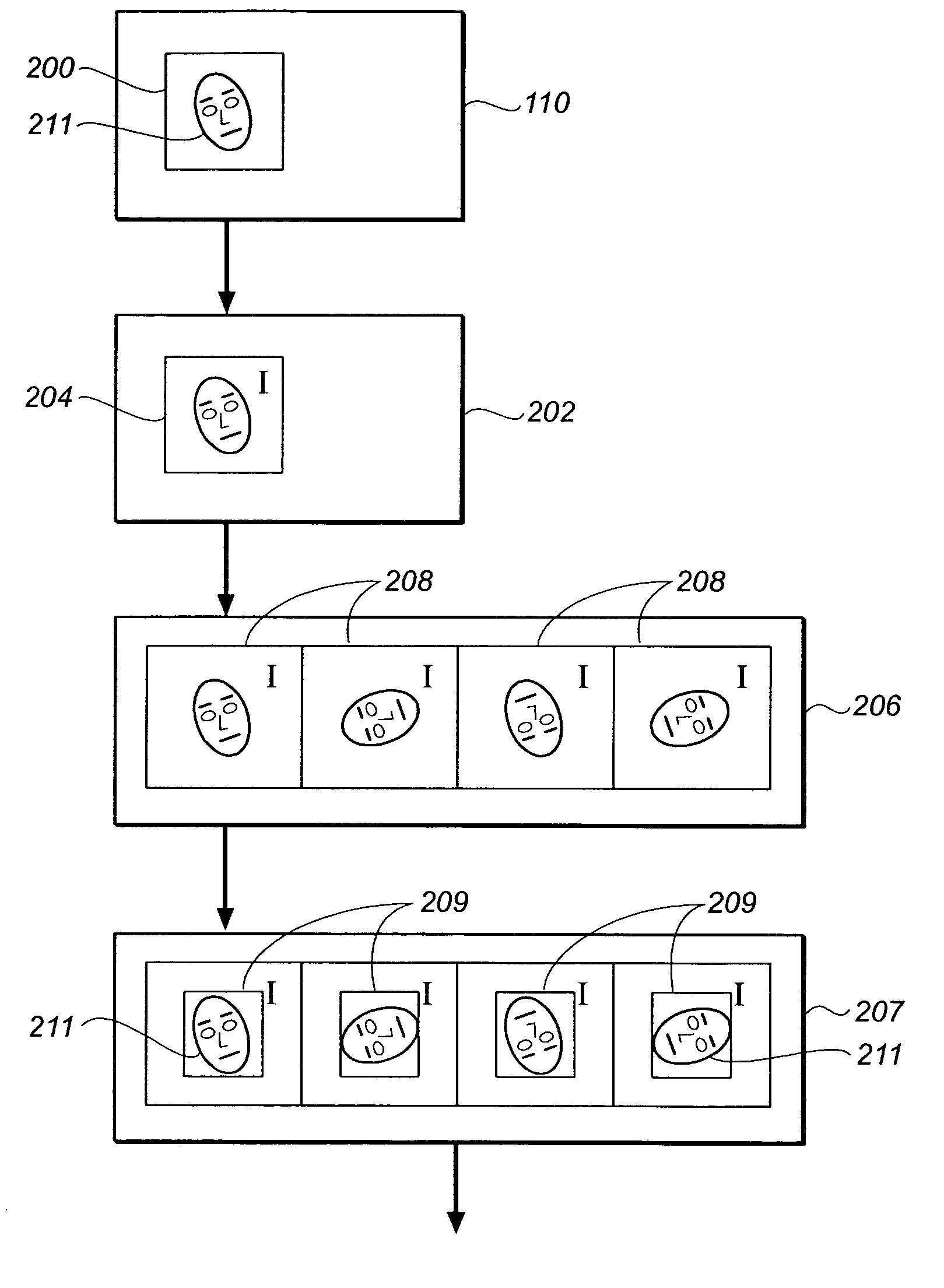
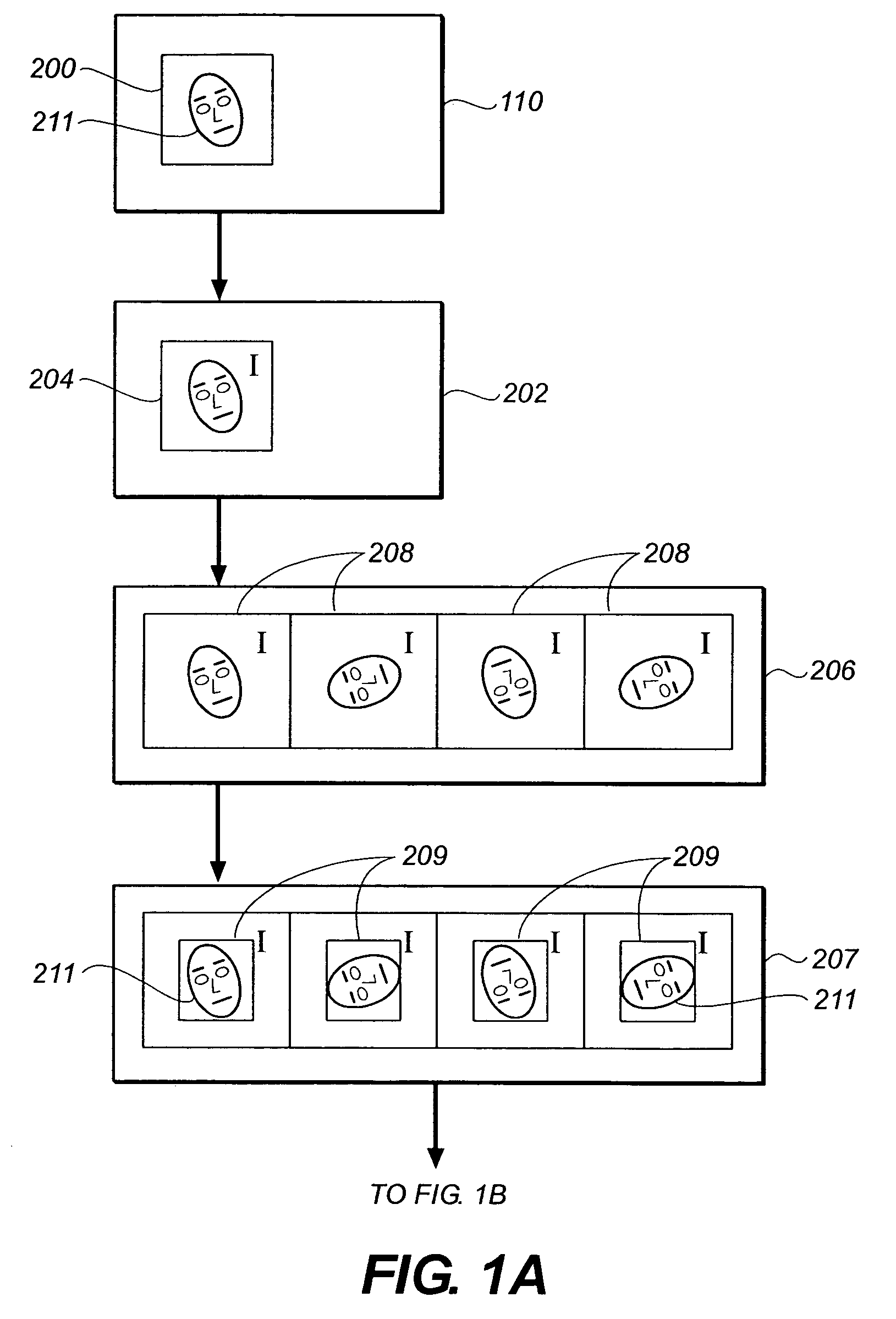
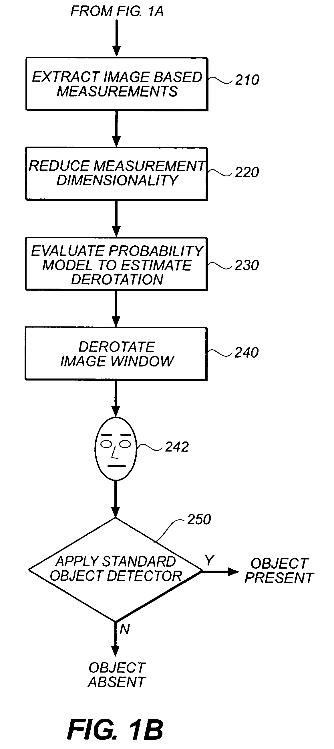
[0032]In the following description, a preferred embodiment of the present invention will be described in terms that would ordinarily be implemented as a software program. Those skilled in the art will readily recognize that the equivalent of such software may also be constructed in hardware. Because image manipulation algorithms and systems are well known, the present description will be directed in particular to algorithms and systems forming part of, or cooperating more directly with, the system and method in accordance with the present invention. Other aspects of such algorithms and systems, and hardware and / or software for producing and otherwise processing the image signals involved therewith, not specifically shown or described herein, may be selected from such systems, algorithms, components and elements known in the art. Given the system as described according to the invention in the following materials, software not specifically shown, suggested or described herein that is ...


PUM


Abstract

In methods, systems, and computer program products for locating a regularly configured object within a digital image, a plurality of primary rotated integral images of the digital image are computed. Each primary rotated integral image has a different in-plane rotation. A set of secondary rotated integral images are derived from each of the primary rotated integral images. The secondary rotated integral images have further in-plane rotations relative to the respective primary rotated integral image. A window is defined within the digital image and corresponding windows of the rotated integral images. The values of convolution sums of a predetermined set of feature boxes within the window, in each of the rotated integral images are extracted. The dimensionality of the convolution sums is reduced to provide a set of reduced sums. A probability model is applied to the reduced sums to provide a best estimated derotated image of the window.

Description

FIELD OF THE INVENTION[0001]The invention relates generally to the field of digital image processing, and in particular to a method and apparatus for finding objects in an image, where the method applies regardless of the in-plane rotational orientation of objects in the image.BACKGROUND OF THE INVENTION[0002]Much recent research in the computer vision field concerns the abilities to find “regularly configured objects” (also referred to hereafter by the shorter term “objects”) in digital images. Objects can be defined as classes of real-world entities that obey consistent rules with respect to geometric shape and appearance. Examples of objects includes human faces, whole people, cars, animals, and buildings.[0003]The ability to computationally find objects in images varies directly with the extrinsic and intrinsic consistency of the class appearance. “Extrinsic consistency” refers to factors, such as lighting and pose, that can vary dramatically and are independent of the physical ...

Claims


Application Information

Patent Timeline
Patent Type & Authority Patents(United States)
IPC IPC(8): G06K9/32G06K9/00G06K9/62G06K9/64
CPCG06K9/00248G06K9/6211G06V40/165G06V10/757
Inventor NICPONSKI, HENRY
Owner MONUMENT PEAK VENTURES LLC
Why Eureka
Try Eureka