
Middle-arranged magnetic steel magnetic circuit structure with inclined surface contact

A technology of magnetic steel and slope, applied in the direction of circuits, electromagnetic relays, electromagnetic relay details, etc., can solve the problems of poor anti-vibration performance, small contact projection area, small electromagnetic attraction, etc., to achieve increased anti-vibration performance and improved vibration performance Index, the effect of meeting the requirements of the vibration index

Pending Publication Date: 2020-07-03
贵州振华群英电器有限公司(国营第八九一厂)
View PDF5 Cites 2 Cited by
  • Summary
  • Abstract
  • Description
  • Claims
  • Application Information

AI Technical Summary

Problems solved by technology

[0002] At present, most of the double-coil magnetic holding contactors on the market adopt a planar contact structure on the magnetic circuit part of the armature and the iron core. Due to the planar contact of this structure, the contact projected area is small, resulting in a relatively small initial electromagnetic attraction force of the entire magnetic circuit part. Small, small electromagnetic attraction leads to low stiffness of the main compression spring on the product, and small spring stiffness provides small mechanical reaction force, so the anti-vibration performance of the whole product is poor, which cannot meet the growing anti-vibration performance indicators of aviation contactors requirements

Method used


Image

  • Middle-arranged magnetic steel magnetic circuit structure with inclined surface contact
  • Middle-arranged magnetic steel magnetic circuit structure with inclined surface contact
  • Middle-arranged magnetic steel magnetic circuit structure with inclined surface contact

Examples


Embodiment Construction

[0016] The technical solutions provided by the present invention will be further described in detail in conjunction with specific embodiments and accompanying drawings.

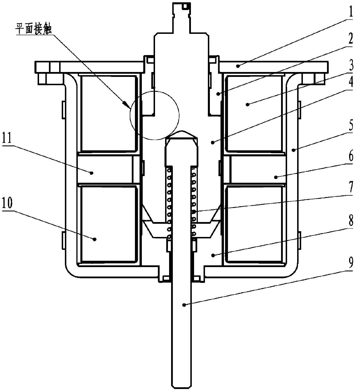
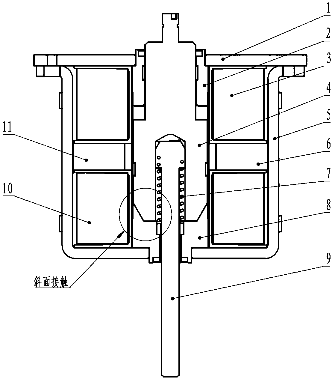
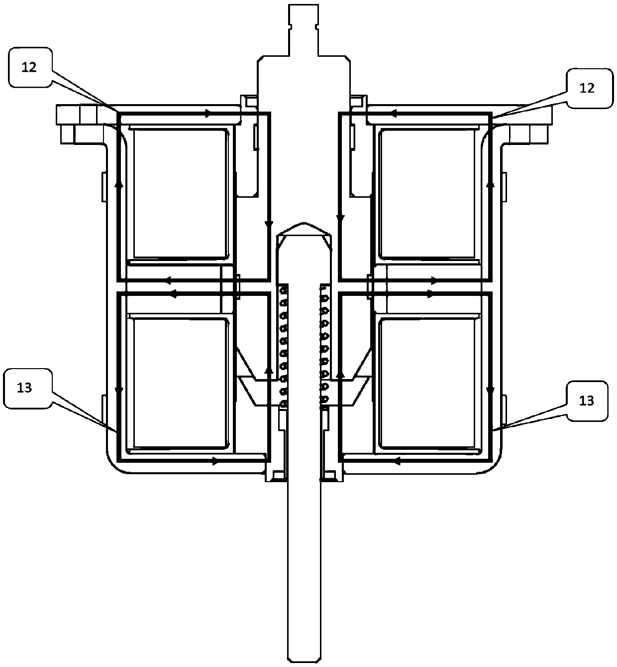
[0017] like Figure 1-2 As shown, the magnetic circuit structure of the middle magnetic steel with inclined surface contact provided by the present invention includes an upper iron core 2, a lower iron core 8, an armature 4, a transmission rod 9 and a magnetic part for providing a magnetic circuit, and the upper iron core 2 The plane contact with the armature 4, the slope contact between the lower iron core 8 and the armature 4, one end of the transmission rod 9 and the armature 4 are riveted together by rivets to form the armature part, and the main compression spring 7 is arranged between the two; The magnetic part is located on the outer periphery of the upper iron core 2 and the lower iron core 8 .

[0018] Here, the side of the armature 4 in contact with the lower iron core 8 is a bevel chamfer structur...


PUM


Abstract

The invention discloses a middle-arranged magnetic steel magnetic circuit structure with inclined surface contact. The magnetic circuit structure comprises an upper iron core (2), a lower iron core (8), an armature (4), a transmission rod (9) and a magnetic part for providing a generated magnetic loop, wherein the upper iron core (2) and the armature (4) are in plane contact, the lower iron core (8) and the armature (4) are in inclined surface contact, one end of the transmission rod (9) is connected with the armature (4), a main pressure spring (7) is arranged between the transmission rod (9)and the armature (4), and the magnetic part is positioned at the peripheries of the upper iron core (2) and the lower iron core (8). According to the invention, the contact surface of the armature end surface of the magnetic circuit structure and the lower iron core adopts an inclined surface structure, so that the initial electromagnetic attraction force is increased by more than one time compared with the plane contact structure, and the rigidity of the spring can be doubled due to the fact that the electromagnetic attraction force is doubled so as to double the vibration resistance of theproduct, substantially improve the vibration performance index and meet the vibration index requirement of the aerospace contactor.

Description

technical field [0001] The invention relates to a magnetic circuit structure of a magnetic holding contactor, in particular to a magnetic circuit structure of a middle-mounted magnetic steel with inclined surface contact. Background technique [0002] At present, most of the double-coil magnetic holding contactors on the market adopt a planar contact structure on the magnetic circuit part of the armature and the iron core. Due to the planar contact of this structure, the contact projected area is small, resulting in a relatively small initial electromagnetic attraction force of the entire magnetic circuit part. Small, small electromagnetic attraction leads to low stiffness of the main compression spring on the product, and small spring stiffness provides small mechanical reaction force, so the anti-vibration performance of the whole product is poor, which cannot meet the growing anti-vibration performance indicators of aviation contactors requirements. Contents of the inve...

Claims


Application Information

Patent Timeline
IPC IPC(8): H01H50/18H01H50/30
CPCH01H50/18H01H50/30
Inventor 周敬姚茂吉郑绍信何云山王江勇邵将杨帆熊林
Owner 贵州振华群英电器有限公司(国营第八九一厂)
Learn More