
A charging structure, charging method and terminal

A charging structure and charging plug technology, applied in the direction of battery disconnection circuit, battery circuit device, circuit, etc., can solve hidden safety hazards, reduce the service life of terminal batteries, and damage the performance of terminal batteries, so as to prolong the service life and avoid battery The effect of performance impairment

Active Publication Date: 2021-09-28
HUIZHOU TCL MOBILE COMM CO LTD
View PDF0 Cites 0 Cited by
  • Summary
  • Abstract
  • Description
  • Claims
  • Application Information

AI Technical Summary

Problems solved by technology

Nowadays, terminals such as mobile phones and tablet computers have become electronic devices that people carry with them every day, especially the emergence of more and more large-screen touch-screen smart phones has promoted the development of the terminal entertainment industry, such as game software, video software, work software, etc. , the performance of mobile phones is getting higher and higher, causing the terminal power consumption to be fast, requiring users to frequently charge the terminal
[0003] At present, the USB charging interface of conventional terminals is in the manual plug-in mode. When the battery is fully charged, the USB charging cable needs to be pulled out manually. When the charging is completed, it may not be possible to disconnect the terminal from the USB charging cable in time due to various reasons. Connecting, charging for a long time will damage the battery performance of the terminal, reduce the service life of the terminal battery, and have certain safety hazards

Method used


Image

  • A charging structure, charging method and terminal
  • A charging structure, charging method and terminal
  • A charging structure, charging method and terminal

Examples


Embodiment Construction

[0039] Books and other terms in the above figures and the description of the embodiments of the present invention claimed in claims as "first", "second" are used for distinguishing between similar objects, and not necessarily for describing a particular sequential or priorities. It should be understood that the data so used are interchangeable under appropriate circumstances, to be able to be implemented in embodiments other than illustrated or described herein the content of the order embodiment herein described. Next, the technical solutions in the embodiments of the present invention will be apparent from the embodiment of the present invention, and it is clearly described, and it is understood that the described embodiments are merely embodiments of the present invention, not all of the embodiments. Based on the embodiments of the present invention, those skilled in the art are in the range of the present invention in the scope of the present invention without all other embodi...


PUM


Abstract

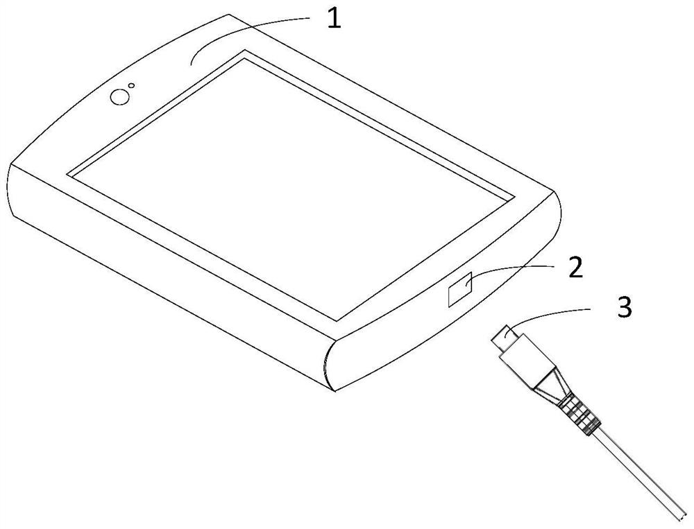
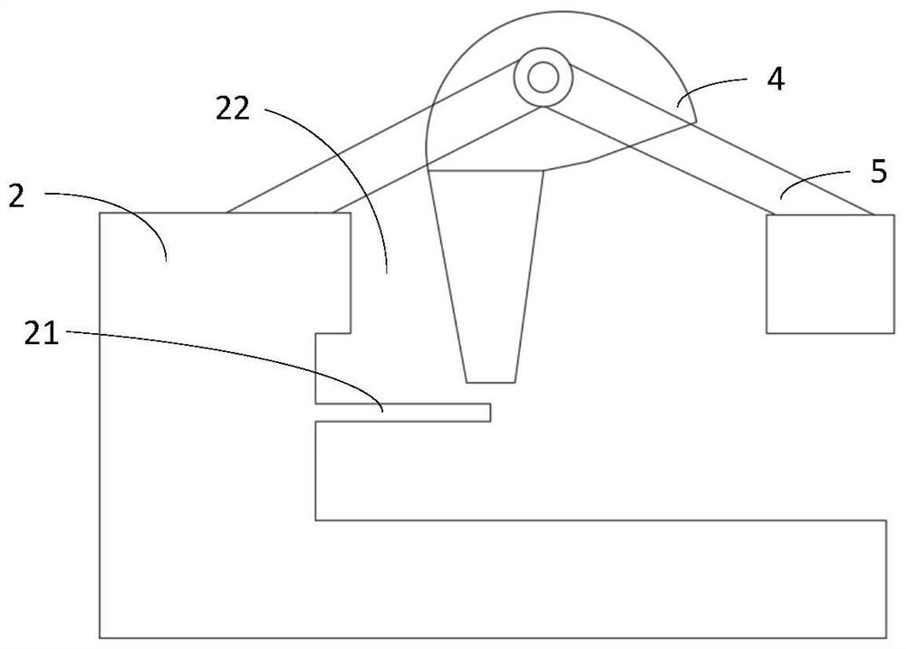
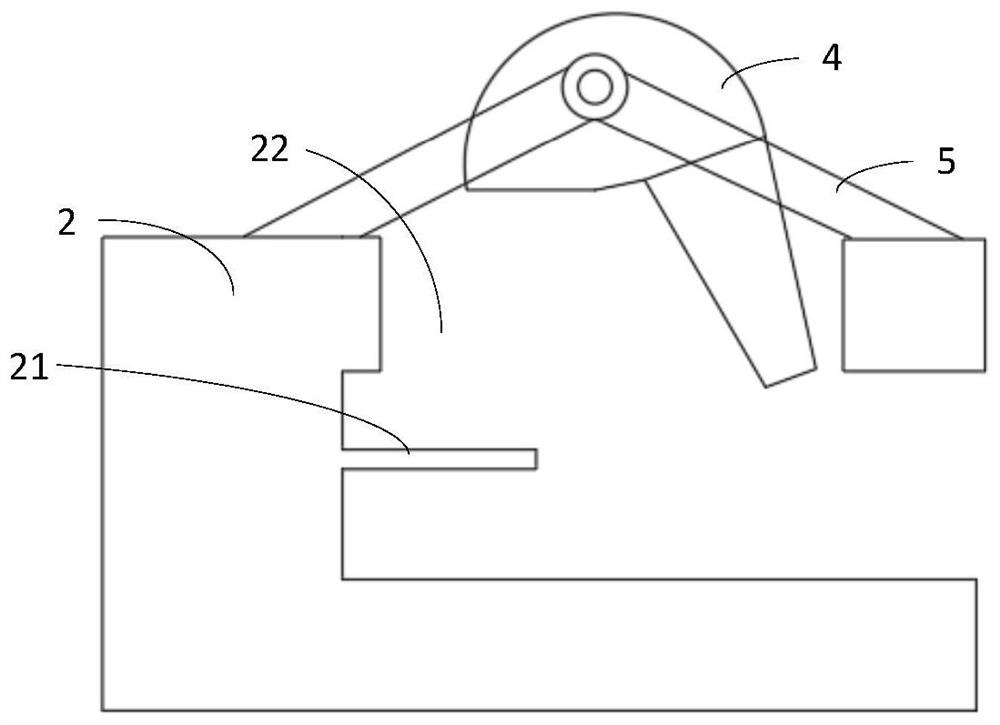
Embodiments of the present invention provide a charging structure, a charging method, and a terminal. The charging structure includes: a charging socket and a limiting component. The charging socket includes socket connecting pins and through holes, and the socket connecting pins are used to communicate with The plug connecting pins of the charging plug are electrically connected, the first end of the limiting component is located above the connecting pin of the socket, the first end of the limiting component is used to push the charging plug, and the second end of the limiting component is located on the socket. Above the charging plug, the second end of the limiting component is used to limit the charging plug; the charging method includes: detecting the current battery voltage; when the battery voltage exceeds a preset voltage threshold, start an electric motor to drive the limiting component to rotate , Disconnect the socket connection pin from the plug connection pin to stop charging; after the terminal device is fully charged, automatically disconnect the electrical connection between the terminal charging socket and the charging plug to avoid overcharging on the battery performance of the terminal battery damage and prolong battery life.

Description

Technical field [0001] Example The present invention relates to a mobile terminal, particularly to a charging structure, a charging method and a terminal. Background technique [0002] With the large number of popular applications continue development of communication technology, smart phones, tablet PCs and notebook computers, terminals, terminal toward diversification, the development direction of personalized increasingly become indispensable in the life and work terminal. Today, mobile phones, tablet PCs and other terminals have become a daily portable electronic devices, especially as more and more large-screen touch-screen smart phones appear to promote the development of the terminal entertainment industry, such as game software, video software, and other software work , the phone's increasingly high performance, resulting in fast terminal power consumption, requiring users to frequently recharge the terminal. [0003] Currently, conventional USB charging interface termina...

Claims


Application Information

Patent Timeline
Patent Type & Authority Patents(China)
IPC IPC(8): H02J7/00H01R13/629
CPCH01R13/62944H02J7/0031H02J7/0045
Inventor 陈卫马妮娜白松
Owner HUIZHOU TCL MOBILE COMM CO LTD
Learn More