
Connecting rod mechanism and robot

A link mechanism and robot technology, applied in the field of robots, can solve problems such as large thrust

Inactive Publication Date: 2020-07-07
UBTECH ROBOTICS CORP LTD
View PDF10 Cites 0 Cited by
  • Summary
  • Abstract
  • Description
  • Claims
  • Application Information

AI Technical Summary

Problems solved by technology

[0004] The purpose of the present invention is to provide a link mechanism, aiming to solve the technical problem that the current link mechanism needs to rotate a large angle and cause its thrust to be very large

Method used


Image

  • Connecting rod mechanism and robot
  • Connecting rod mechanism and robot
  • Connecting rod mechanism and robot

Examples


Embodiment Construction

[0043] In order to make the object, technical solution and advantages of the present invention clearer, the present invention will be further described in detail below in conjunction with the accompanying drawings and embodiments. It should be understood that the specific embodiments described here are only used to explain the present invention, not to limit the present invention.

[0044] It should be noted that when a component is referred to as being “fixed on” or “disposed on” another component, it may be directly or indirectly on the other component. When an element is referred to as being "connected to" another element, it can be directly or indirectly connected to the other element.

[0045] The orientation or positional relationship indicated by the terms "upper", "lower", "left", "right", etc. are based on the orientation or positional relationship shown in the drawings, and are for convenience of description only, rather than indicating or implying the referred devic...


PUM


Abstract

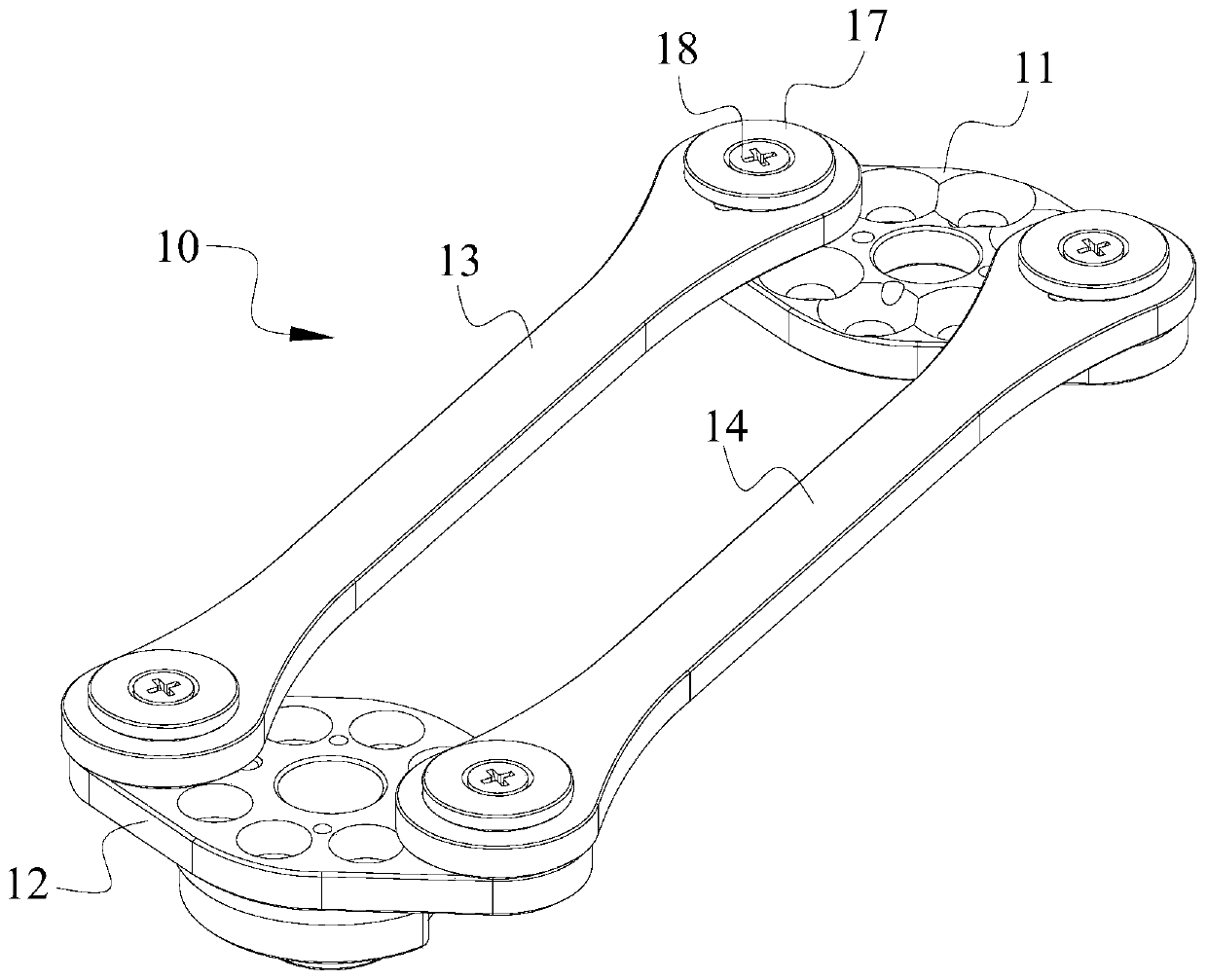
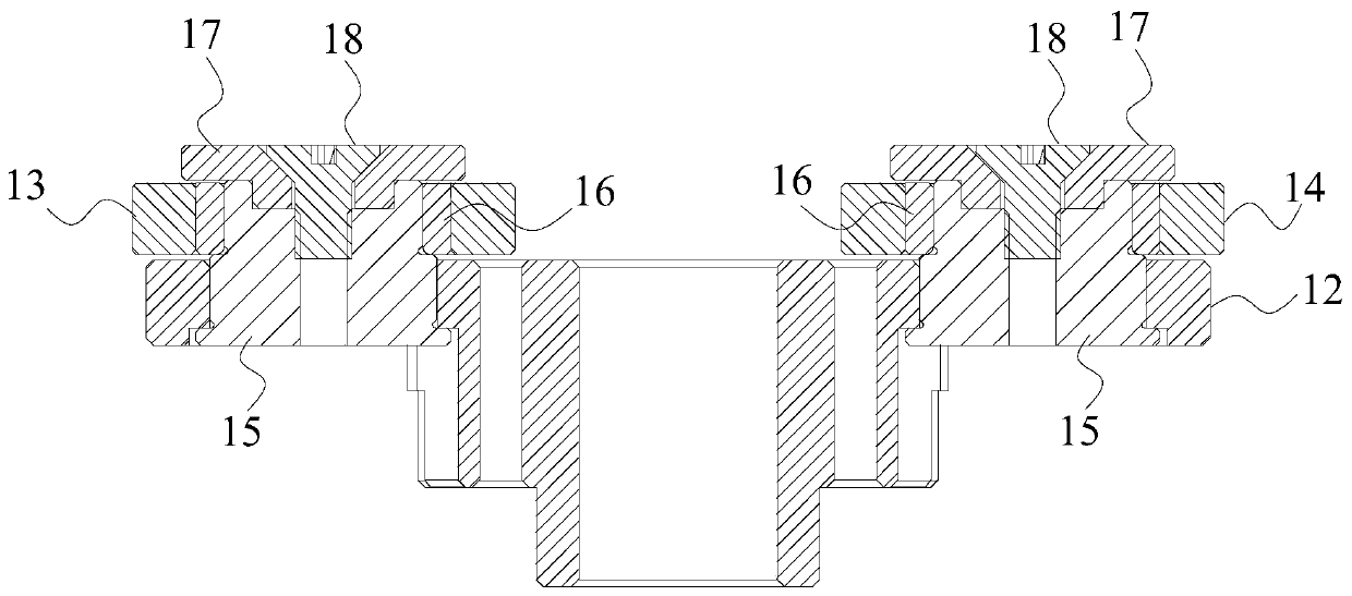
The invention is suitable for the technical field of robots, and provides a connecting rod mechanism and a robot. The connecting rod mechanism comprises a first connecting rod support, a second connecting rod support, a first connecting rod and a second connecting rod, wherein the second connecting rod support is arranged opposite to the first connecting rod support; two ends of the first connecting rod are respectively connected with the first connecting rod support and the second connecting rod support in a sliding manner; the second connecting rod is arranged opposite to the first connecting rod, and the two ends of the second connecting rod are slidably connected with the first connecting rod support and the second connecting rod support respectively; a quadrangle is defined by the first connecting rod support, the first connecting rod, the second connecting rod support and the second connecting rod, and initial angles are formed between the first connecting rod support and the horizontal plane and between the second connecting rod support and the horizontal plane. According to the invention, the initial angles are formed between the first connecting rod support and the horizontal plane and between the second connecting rod support and the horizontal plane, so that the connecting rod mechanism can swing forwards to a preset position without rotating by a large angle, and the push-pull force of the connecting rod can be effectively reduced.

Description

technical field [0001] The invention relates to the technical field of robots, in particular to a link mechanism and a robot. Background technique [0002] A robot is a machine device that performs work automatically. It can accept human commands, run pre-programmed programs, and act according to principles and programs formulated with artificial intelligence technology. Its task is to assist or replace human work, such as life. industry, construction, or hazardous work. [0003] At present, in the humanoid bionic robot, the leg structure of the robot realizes the forward and backward swing of the lower leg through the linkage mechanism. Generally, the forward swing angle is greater than the backward swing angle, and the initial angle of the linkage mechanism is generally set to zero degrees. When the link mechanism needs to rotate a large angle to realize the forward swing to the preset position, and when the link mechanism rotates a large angle, the push-pull force of the...

Claims


Application Information

Patent Timeline
Patent Type & Authority Applications(China)
IPC IPC(8): B62D57/032
CPCB62D57/032B25J9/1065B25J9/106B25J18/00
Inventor 熊友军李友朋丁宏钰刘梅春庞建新
Owner UBTECH ROBOTICS CORP LTD
Learn More