Beam expanding laser lamp with double-lens scanning structure
A technology of laser lights and double mirrors, applied in the field of laser lights, can solve the problems that laser lights cannot project beams with a diameter of more than 20mm, and cannot scan thick beams.
- Summary
- Abstract
- Description
- Claims
- Application Information
AI Technical Summary
Problems solved by technology
Method used
Image
Examples
no. 1 example
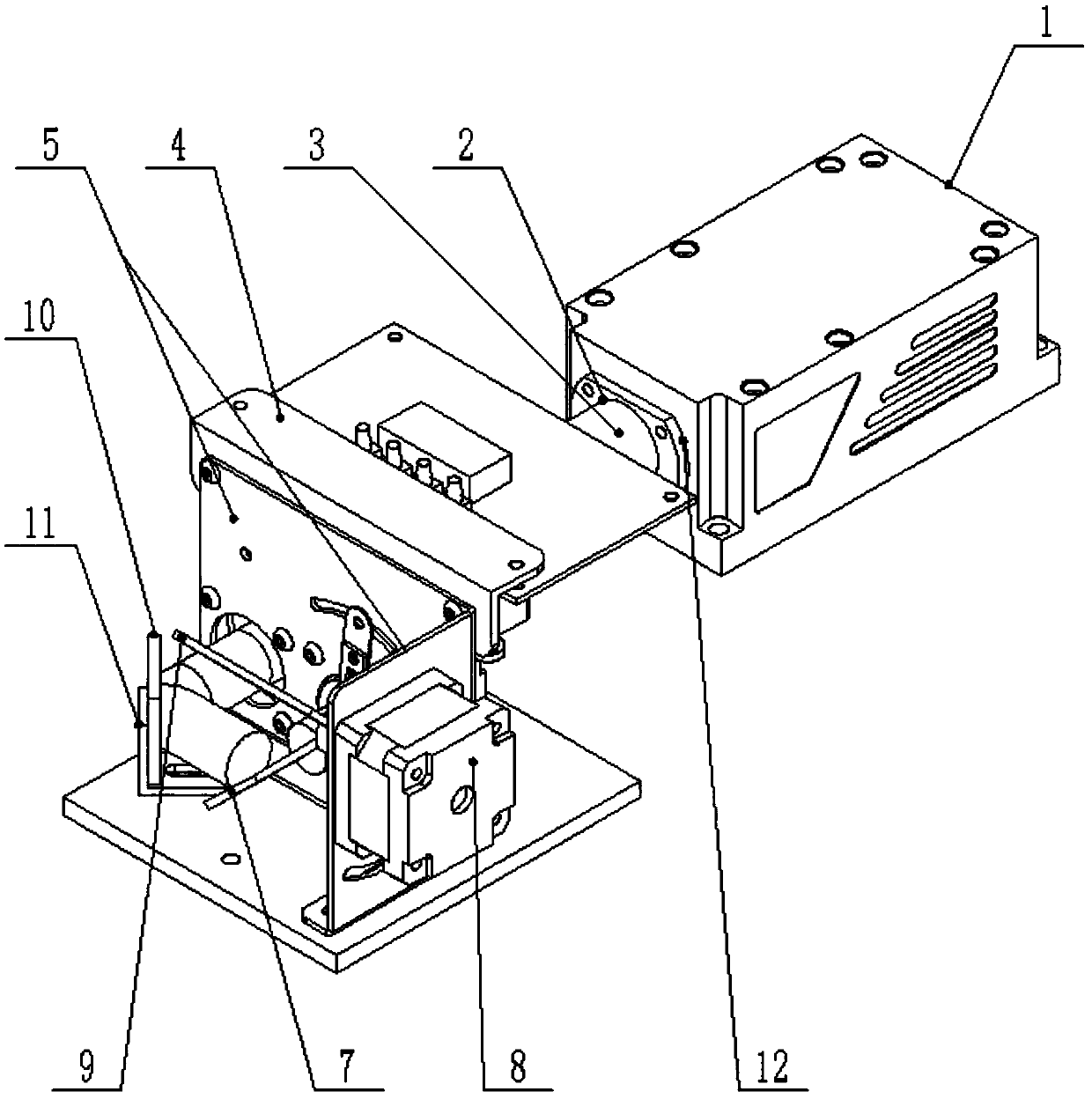
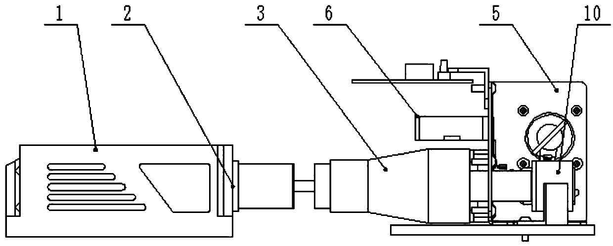
[0025] This embodiment provides a beam expanding laser lamp with a double-mirror scanning structure, such as figure 1 with figure 2 As shown, it includes a laser light box body 1, the side of the laser light box body 1 is a light outlet 2, and the light outlet 2 is connected to a beam expander 3, and the beam expander 3 is connected to a double-mirror scanning structure. The laser beam emitted from the light outlet 2 of the light box body 1 is expanded by the beam expander 3 to reach a diameter of 20 mm to 30 mm, and the expanded coarse beam is scanned by a double-mirror scanning structure before being emitted.
[0026] Specifically, the laser light in the laser light box 1 is emitted to the beam expander 3 through the light outlet 2, and the thin beam (3mm-6mm) is expanded into a coarse beam (20mm-30mm) through the beam expander. The beam is scanned and emitted.
[0027] In particular, the diameter of the beam projected by a conventional laser lamp is about 3 to 6mm. When ...
no. 2 example
[0033] refer to figure 1 , in order to facilitate the installation and support of the reflector 10, an L-shaped plate 11 is installed on the bottom plate of the housing 4, the horizontal plate of the L-shaped plate 11 is closely fixed on the bottom plate of the housing 4, and the vertical plate of the L-shaped plate 11 The plate is perpendicular to the bottom plate of the housing 4, and the reflector 10 is closely mounted on the vertical plate. The optical path of the reflector 10 is as follows: the coarse beam emitted by the beam expander 3 enters the reflector 10 and passes through the reflector 10. The optical path of the rough beam is changed so that the rough beam emitted by the mirror 10 and the rough beam incident on the mirror 10 form an angle of 90° and are parallel to the bottom plate of the housing 4 .
[0034] refer to figure 1 In order to fix the L-shaped plate 11 conveniently, the middle part of the horizontal plate of the L-shaped plate 11 offers a U-shaped thr...
no. 3 example
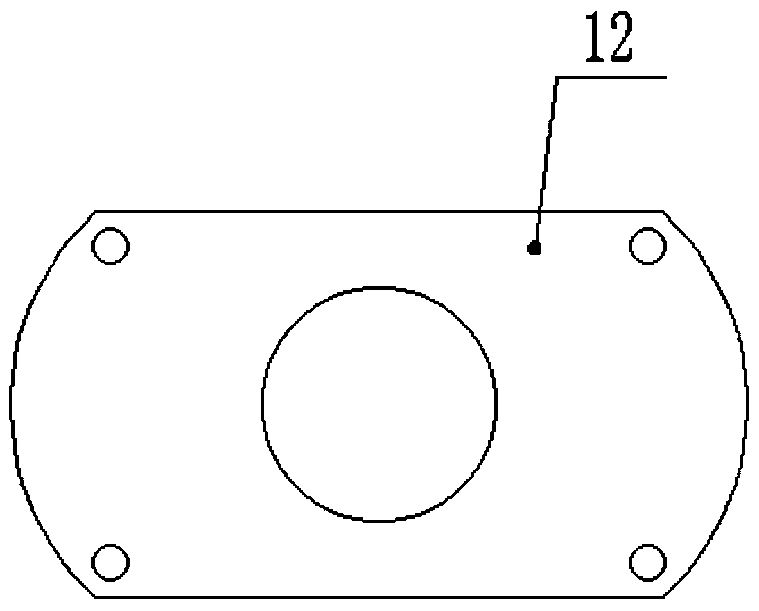
[0036] refer to figure 1 with image 3 , in order to support and strengthen the intensity of the beam expander 3, the light outlet 2 is equipped with a drum-shaped flat plate 12, and the drum-shaped flat plate 12 is tightly mounted on the laser light box 1 by screws, and the center of the drum-shaped flat plate 12 A through hole that can pass through the beam expander 3 is provided, and a sealing ring 14 sleeved on the beam expander 3 is provided between the through hole and the outer surface of the beam expander 3. The sealing ring 14 is to ensure that the beam expander 3 and the The sealing between the through holes prevents light leakage or dust from entering the laser light box body 1 .
[0037] refer to Figure 4 , the circular inner hole wall of the through hole provided in the center of the drum-shaped flat plate 12 is provided with a circle of a plurality of protrusions 13 evenly spaced apart, referring to Figure 5 , the outer wall of the sealing ring 14 is provide...
PUM
| Property | Measurement | Unit |
|---|---|---|
| diameter | aaaaa | aaaaa |
Abstract
Description
Claims
Application Information
 - R&D
- Intellectual Property
- Life Sciences
- Materials
- Tech Scout
- Unparalleled Data Quality
- Higher Quality Content
- 60% Fewer Hallucinations
Browse by: Latest US Patents, China's latest patents, Technical Efficacy Thesaurus, Application Domain, Technology Topic, Popular Technical Reports.
© 2025 PatSnap. All rights reserved.Legal|Privacy policy|Modern Slavery Act Transparency Statement|Sitemap|About US| Contact US: help@patsnap.com


